![]()
1 Ans.
(a). (A)
(b). (A)
(c). (C)
(d). (B)
(e). (A)
(f). (C)
(g). (C)
(h). (C)
2 Ans.
(a)
Mason’s gain formula
Overall system gain is given by
![]()
Pk = gain of k th forward path
Δ = det of the graph
= 1 – sum of loop gains of all individual loops + (sum of gain products of all possible combinations of two non-touching loops) –(sum of gain products of all possible combinations of three non touching loops)+ ……
![]() = the value of Δ for that
part of the graph not touching the kth forward path.
= the value of Δ for that
part of the graph not touching the kth forward path.
(b) 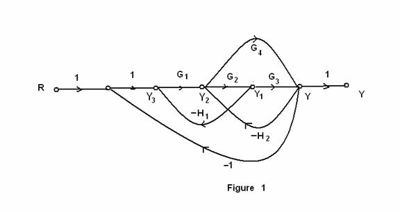

There are no non touching loops
Δ = ![]()
P1 Δ1 + P2 Δ2
T = ----------------------
Δ
Transfer function=![]()
Q. 3
k
-----------------
C(s) (kp+Js)s k k/J
-------- = ---------------------------- = ------------------------ = --------------------
k Js2 + kps + k s2 + kp/Js +k/J
Y(s) 1 + --------------
(kp+Js)s
k
G(s) = ------------------ J = 1 kg-m2
s2 +kps + k
25% = peakover shoot
which gives ξ = 0.403
![]()
peak time = ---- = 2 ![]() = 3.14/2
= 3.14/2
![]()
![]() = 1.71
= 1.71 ![]() 2 = k
2 = k
k=2.94 2 ξ ![]() =kp
=kp
2 ξ![]() 2 ξ
2 ξ ![]()
p = --------- = ----------- = 0.47
k ![]() 2
2
4 Ans.
5(s+20)
G(s) = -----------------------------------------
s(s+4.59)(s2 +3.41s+16.35)
G(s) 5(s+20)
M(s) = -------------- = ------------------------------------------------------
1 + G(s) (s2+4.59s)(s2+3.41s+16.35)+5s+100
5(s+20)
= -----------------------------------
s4+8s3+32s2+80.04s+100
C(s)
----- = M(s) C(s) = 1/sM(s)
R(s)
5s+100
C(s) = -------------------------------------------
s(s4+8s3+32s2+80.04s+100)
Applying inverse laplace transform
C(t) = 1+3/8e-tcos(3t) – 17/24 e-tsin(3t) - 11/8e(-3t) cost -13/8 e-3tsint
s(5s+100)
Css = lim c(t) = lim sC(s) = lim -------------------------------------------
t→ ∞ s→0 s→0 s(s4+8s3+32s2+80.04s+100)
100
= ------ = 1
100
5 Ans.
(a) s4 +2s3+(4+k)s2+9s+25 = 0
Routh array is:
|
s4 |
1 (4+k) 25 |
|
s3 |
2 9 0 |
|
s2 |
(-1+2k)/2 25 0 |
|
s1 |
(18k-109)/(2k-1) 0 |
|
s0 |
25 |
For stability:
-1+2k>0
2k>1
k>1/2
18k -109 >0 k>109/18
so, the range of k for stability is k>6.05
(b)
for k= 100
The characterstic equation is given as
s4 +2s3+104s2+9s+25 =0
|
s4 |
1 104 25 |
|
s3 |
2 9 0 |
|
s2 |
49.5 25 0 |
|
s1 |
8.49 0 |
|
s0 |
25 |
As the first columns are all positive
So., no roots are in right half.
6 Ans
Considering the basic control configuration, wherein the controller input is the error between the desired output and the actual output.
METHOD 1.
This method is applicable only if dynamic model of plant is not available and step response of the plant is S-shaped curve .Then tuning done by Zeigler –Nichols method.
Procedure: obtaining the step response, from that find the dead time (L) and time constant (T)
Then the values of controller is given by
Proportional gain (![]() ) =1.2(T/L)
) =1.2(T/L)
Integral time constant =2L
Derivative time constant=0.5L
Note: There are no specific tuning method available if plant model is not known and step response is not S-shaped curve.
METHOD 2.
This method is applicable only if dynamic model of plant is known and no integral term in the transfer function.
Procedure: Find the critical gain (K) and critical time period (T) at which the system is oscillating using routh array or root locus.
Then the controller parameters are given by
Proportional gain = 0.6 K
Integral time constant=0.5 T
Derivative time constant= 0.125 T
METHOD 3.
This method is applicable only dynamic model of the plant has an integral term in the transfer function.
If the critical period and the gain cannot be calculated , then tuning is done through root locus method.
7 Ans
k
G(s) = ----------------------
s(s+1)(s2+4s+13)
Poles s=0, -1,-2±j3
n=4,m=0
± 180(2q+1)
angle of asymptotes = ----------------- = ±45, ±135
(n-m)
-2-2-1
centroid = -------------- = -1.25
4
4
M(s) = ------------------------
(s2+s)(s2+4s+13)+k
char eqn s4+4s3+13s2+s3+4s2+13s+k = 0
k = -(s4+5s3+17s2+13s)
dk/ds = -(4s3+15s2+34s+13) = 0
so, s= -0.4664, -1.6418±j2.067
so, the break away point is -0.4664
Angle of departures
For complex poles
Ø1= 90, Ø2 = 180 –![]() (3/1), Ø3 = 180 –
(3/1), Ø3 = 180 – ![]() (3/2)
(3/2)
So., at A
= ![]() – (Ø1+ Ø2+ Ø3)
– (Ø1+ Ø2+ Ø3)
= -![]()
and A* = ![]()
Figure Root Locus
k
8 Ans. G(s) = -----------------------
s(1+0.1s)(1+0.5s)
k
G(jw) = -----------------------
jw(1+0.1jw)(1+0.5jw)
corner frequencies:2,10.
|
|
1 |
2 |
10 |
20 |
100 |
|
Magnitude db/dec |
-20 |
-40 |
-60 |
-60 |
-60 |
|
phase |
-122.27 |
-146.3 |
-216 |
-238 |
-263 |
Let k =1 then GM at this k = 20 dB
9 Ans.
k 0.05k
G(s)H(s)= -------------------- = ---------------------
s(s+2)(s+10) s(1+0.5s)(1+0.1s)
mapping ![]()
w → 0 to +∞
0.05k
G(jw)H(jw) = ------------------------------
-0.6w2 + jw(1-0.05w2)
at w=![]() imaginary is zero
imaginary is zero
1-0.05w2 =0 ![]() =4.472 rad/sec.
=4.472 rad/sec.
at ![]()
GH = -.00417k
Mapping ![]()
K
GH(s) = ------ = 0![]() at s= lim Rej
θ
at s= lim Rej
θ
s3 R→ ∞
When
θ = ![]() /2
G(s)H(s) = 0
/2
G(s)H(s) = 0![]()
θ =- ![]() /2
G(s)H(s) = 0
/2
G(s)H(s) = 0![]()
Mapping ![]()
W → - ∞ to 0
It is mirror image of ![]() mapping
mapping
Mapping ![]()
For s= lim Rej θ
R→0
θ = - ![]() /2 G(s)H(s) =
∞
/2 G(s)H(s) =
∞![]()
θ = ![]() /2 G(s)H(s)
= ∞
/2 G(s)H(s)
= ∞![]()
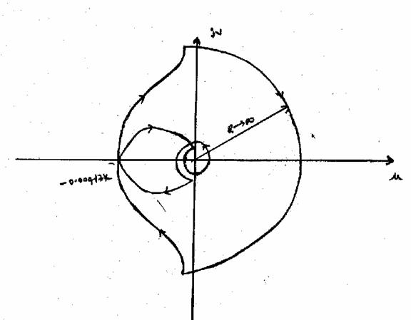
FIGURE: NYQUIST PLOT
Range of values of k for the system to be stable. Limiting value of k
-0.00417k = -1 k = 240
So when k<240 the closed loop system is stable.
10 Ans.
(a)
1 1
G(s) = ---------------- H(s) = --------
s2 + s+2 (s+1)
R(s)
E(s) = ------------------ ![]() = lim sE(s)
= lim sE(s)
1 + G(s)H(s) s→0
for unit step input
s*1/s
![]() = lim
-----------------------------
= lim
-----------------------------
s→0 1 + (1/s2+s+2)(1/s+!)
1
= ----------------------- = 2/3
1 +( ½)
for unit ramp input
s*1/![]()
![]() = lim ------------------------ =
∞
= lim ------------------------ =
∞
s→0 1 + G(s)H(s)
for unit parabolic input
s*1/s3
![]() = lim ------------------- =
∞
= lim ------------------- =
∞
s→0 1 + G(s)H(s)
C(s) G(S) 1/(s2 + s+2)
----- = --------------------- = ---------------------------------
R(s) 1+ G(S)H(s) 1 + (1/s2+s+2)(1/s+1)
(s+1)
= --------------------------------
(s2+s+2)(s+1)+1
(s+1)
= -----------------------------
s3+2s2+3s+3
(b). impulse response of the system:
11 Ans.
(i)
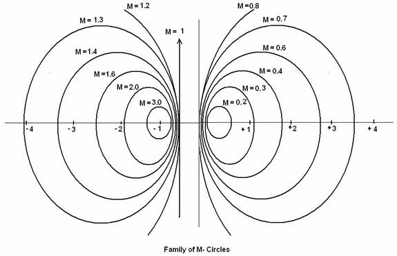
Constant M and N circles:
The magnitude of closed loop transfer function with unity feedback can be shown to be in the form of circle for every value of M. these circles are called M-circles.
If the phase of closed loop transfer function with unity feedback is α, then it can be shown that tan α will be on the form of circle for every value of α. These circles are called N- circles.
The M and N circles are used to find the closed loop frequency response graphically form the open loop frequency response G(jw) without calculating the magnitude and phase of the closed loop transfer for at each frequency .
For M circles:
Consider the closed loop transfer function of unity feedback system.
C(s) / R(s) = G(s) / 1+G(s)
Put s = jw;
C(jw) /R(jw) =G(jw) / 1 + G(jw)
( X + M2 / M2-1 )2 + γ2 = ( M2 / M2-1 )2 ---- (1)
The equation of circle with centre at (X1,Y1) and radius r is given by
( X - X1)2 + (Y – Y1 )2 = r2 -----(2)
On comparing eqn (1) and (2)
When M = 0;
X1 = - M2 / M2-1 =0
Y1 = 0
R = M / M2-1 = 0;
When M = ∞
X1 = - M2 / M2-1 = -1
Y1= 0;
R = M / M2-1 = 1/M = 0
When M = 0 the magnitude circle becomes a point at (0, 0)
When M=∞, the magnitude circle becomes a point at (-1, 0)
From above analysis it is clear that magnitude of closed loop transfer function will be in the form of circles when M ¹ 1 and when M=1 , the magnitude is a straight line passing through (-1/2 , 0).
Family of N- circles:
For constant N circles
Tan ![]() = N =
= N = ![]()
Constant N-circles have centre as

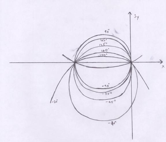
Family of N- circles
(ii)
Working of AC Servomotor:
The symbolic representation of an AC servomotor as a control system is shown in figure. The reference winding is excited by a constant voltage source with a frequency n the range 50 to 1000Hz. By using frequency of 400Hz or higher, the system can be made less susceptible to low frequency noise. Due to this feature, ac drives are extensively used in aircraft and missile control system in which the noise and disturbance often create problems.
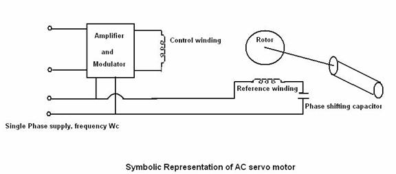
The control winding is excited by the modulated control signals and this voltage is of variable magnitude and polarity. The control signal of the servo loop (or the system) dictates the magnitude and polarity of this voltage.
The control phase voltage is supplied from a servo amplifier and it has a variable magnitude and polarity (+ or – 90o phase angle w.r.t. the reference phase). The direction of rotation of the motor reverses as the polarity of the control phase signal changes sign.
It can be proved that using symmetrical components that the starting torque of a servo motor under unbalanced operation is proportional to E, the rms value of the sinusoidal control voltage e(t). A family of torque-speed characteristics curves with variable rms control voltage is shown in figure. All these curves have negative slope.
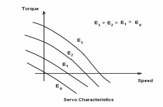
Note that the curve for zero control voltage goes through the origin and the motor develops a decelerating torque.
(iii) Stepper Motor:
A stepper motor transforms electrical pulses into equal increments of shaft motion called steps. It has a wound stator and a non-excited rotor. They are classified as variable reluctance, permanent magnet or hybrid, depending on the type of rotor.
The no of teeth or poles on the rotor and the no of poles on the stator determine the size of the step (called step angle). The step angle is equal to 360 divided by no of step per revolution.
Operating Principle:
Consider a stepper motor having 4-pole stator with 2-phase windings. Let the rotor be made of permanent motor with 2 poles. The stator poles are marked A, B, C and D and they excited with pulses supplied by power transistors. The power transistors are switched by digital controllers a computer. Each control pulse applied by the switching device causes a stepped variation of the magnitude and polarity of voltage fed to the control windings.
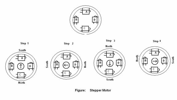
Stepper motors are used in computer peripherals, X-Y plotters, scientific instruments, robots, in machine tools and in quartz-crystal watches.