AMIETE – ET (NEW SCHEME) – Code: AE59
Subject: CIRCUIT THEORY & DESIGN
 Time: 3 Hours
Max. Marks: 100
Time: 3 Hours
Max. Marks: 100
NOTE: There are 9 Questions in all.
· Question 1 is compulsory and
carries 20 marks. Answer to Q.1 must be written in the space provided for it in
the answer book supplied and nowhere else.
· Out of the remaining EIGHT
Questions, answer any FIVE Questions. Each question carries 16 marks.
· Any required data not
explicitly given, may be suitably assumed and stated.
Q.1 Choose
the correct or the best alternative in the following: (2![]() 10)
10)
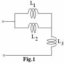
a. What
is the equivalent inductance for the network shown in Fig.1
(A) ![]() (B)
(B) ![]()
(C) ![]() (D)
(D) ![]()
b. When ![]() , the roots of
, the roots of ![]()
(A) real and repeated (B) real and unrepeated
(C) complex (D) imaginary
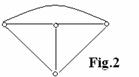
c. For the graph shown in Fig.2 the tree of the
network is
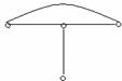
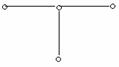
(A) (B)
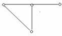
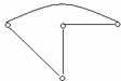
(C) (D)
d. Equivalent of
capacitor with no initial charge at ![]() is
is
(A) short circuit (B) open circuit
(C) voltage source (D) current source
e. Initial value
of function  is
is
(A) 0.5 (B) 0
(C) ![]() (D) 1
(D) 1
f.
(A) ![]() (B)
(B) ![]()
(C) ![]() (D)
(D) ![]()
g. Impulse response of the system when double poles at ![]() is ________.
is ________.
(A) sinusoid of linearly decreasing
amplitude
(B) sinusoid of exponentially
decreasing amplitude
(C) sinusoid of linearly increasing
amplitude
(D) sinusoid of fixed amplitude
h. When two-port
networks are connected in parallel then to characterize the network
_________________.
(A) Short-circuit admittance
parameters are useful
(B) Open-circuit impedance
parameters are useful
(C) hybrid parameters are useful
(D) transmission parameters are
useful
i. RMS value of a periodic wave is defined as
____________.
(A)  (B)
(B) 
(C) ![]() (D) None of the above
(D) None of the above
j. Which one of
the following function is LC immittance?
(A)  (B)
(B) 
(C)  (D)
(D) 
Answer any FIVE Questions out
of EIGHT Questions.
Each question carries 16
marks.
Q.2 a. Explain independent sources. (8)
b. In
the network shown in Fig.3, all sources are time invariant. Determine the branch current in the
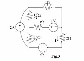
![]() resistor using mesh
current analysis. (8)
resistor using mesh
current analysis. (8)
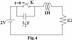
Q.3 a. The network shown in Fig.4 is
in the steady state, with the switch K closed.
At time t = 0, the switch is opened.
Determine the voltage, Vk, across the switch K and also find ![]() at
at ![]() . (6)
. (6)
b. Derive the expression for the transfer
function of single tuned RLC circuit and hence obtain the expression for ![]() (maximum frequency). (10)
(maximum frequency). (10)
Q.4 a. Solve the differential equation using the
 (6)
(6)
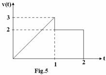
b. The waveform
shown in Fig.5 is nonrecurring. Write an
equation for this waveform and obtain the
c. State
and prove Final Value Theorem as used in
Q.5 a. For the network shown in Fig.6, find the
transform impedance Z(s). (6)
b. In the network
shown in Fig.7, the switch is closed at t=0.
Find the current ![]() in the resistor
in the resistor ![]() by applying Thevenin’s
theorem. (10)
by applying Thevenin’s
theorem. (10)
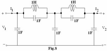
Q.6 a. For
the network shown in Fig.8, show that the voltage-ratio transfer function is  . (8)
. (8)
b. The
network shown in Fig.9, show that the impedance has the form
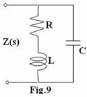
![]() . Determine
. Determine![]() ,
, ![]() &
& ![]() in terms of R, L and
C. If poles are located at
in terms of R, L and
C. If poles are located at ![]() and zero at
and zero at ![]() 3
with
3
with ![]() , find the values for R, L & C. (8)
, find the values for R, L & C. (8)
Q.7
a. Obtain the relations between Z parameters in terms of the transmission
parameters, for any generic network. (7)
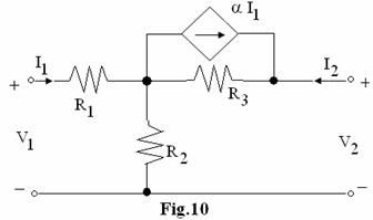
b. For the
network shown in Fig.10, obtain the h-parameters. (9)
Q.8 a. Synthesize
the network for the following function in Foster form ![]() (10)
(10)
b. Synthesize the
Cauer form such that the inductor is in series arm and the capacitor is in
shunt arm of the function  . (6)
. (6)
Q.9 a. Synthesize the voltage ratio  as a
constant-resistance bridged-T network terminated in a
as a
constant-resistance bridged-T network terminated in a ![]() resistor. (8)
resistor. (8)
b. Give the
design procedure of bandpass filter from low pass filter by frequency
transformation. (8)