AMIETE – ET (OLD SCHEME)
Code: AE08 Subject: CIRCUIT THEORY & DESIGN
 Time: 3 Hours
Max. Marks: 100
Time: 3 Hours
Max. Marks: 100
NOTE: There are 9 Questions in all.
· Question 1 is compulsory and
carries 20 marks. Answer to Q.1 must be written in the space provided for it in
the answer book supplied and nowhere else.
· Out of the remaining EIGHT
Questions answer any FIVE Questions. Each question carries 16 marks.
· Any required data not explicitly
given, may be suitably assumed and stated.
Q.1 Choose
the correct or the best alternative in the following: (2![]() 10)
10)
a. The current through 2![]() register
in the Fig.1 is:
register
in the Fig.1 is:
(A)
3 (B)
2
(C) 1 (D) 0
b. Time constant of a capacitance circuit may be defined as the time during which voltage
(A)
rises to 63.2% of its final steady value
(B) rises
to 38.6% of its final steady value
(C) falls to 38.6% of its final steady value
(D) 50% of its final steady state value.
c. A capacitor used in 240 volt AC line should have a peak voltage rating of
(A) 240 volts (B)
340 volts
(C) 120 volts (D)
720 volts
d. If
four resistors each of 4 k![]() are connected in parallel, the net resistance is
are connected in parallel, the net resistance is
(A)
1 k![]() (B)
16 k
(B)
16 k![]()
(C) 2 k![]() (D)
8 k
(D)
8 k![]()
e. In the circuit VS = 10 cos![]() t, power drawn by the 2 ohm resistor in 4 watt. The power
factor is
t, power drawn by the 2 ohm resistor in 4 watt. The power
factor is
(A) 0.3 (B)
0.4
(C) 0.6 (D)
0.8
f. Kirchoff’s voltage law cannot be used
(A) with parallel circuit
(B) to find current in a circuit
(C) to find voltage across a resistor in a series
circuit
(D) for non-linear circuits
g. In RLC circuit, the current at resonance is
(A) maximum in parallel resonance
and minimum in series resonance. (B) maximum in series
resonance and minimum in parallel resonance.
(C) maximum in both series and parallel
resonance.
(D) minimum in both series and parallel
resonance.
h. The
current in the 12 ![]() resistor in the
following circuit (Fig.2) is given by
resistor in the
following circuit (Fig.2) is given by
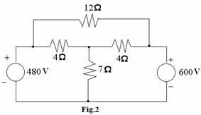
(A) 10 amp from left
to right (B) 10 amp from right to left
(C) 5
amp from left to right (D) 5 amp from right to left
i. If the load connected to the source is inductive, for a maximum transfer of power from source to load, the source impedance should be
(A) Inductive (B) capacitive
(C) Resistive (D)
combination of L and C
j. Kirchoff’s current law is valid for
(A) DC circuits only (B) AC circuits only
(C) Both DC and AC circuits (D) Sinusoidal sources
only
Answer
any FIVE Questions out of EIGHT Questions.
Each
question carries 16 marks.
Q.2 a. Explain Duality and find dual of the given
network (Fig.3). (3+3)
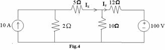
b. Determine Ix and Iy in
the Fig. 4, using Kirchoff’s law. (5)
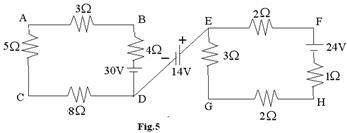
c. For
the circuit Fig. 5, find VBG using Nodal analysis. (5)
Q.3 a. What
do you mean by Initial conditions? (4+4)
Switch ‘S’ in the circuit shown in Fig. 6 below is closed at
t=0.
Determine the initial value of i, di/dt and d2i/dt2
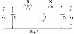
b. In the network shown in Fig.7, initial
voltage on C1 is V1 and on C2 is V2, such that V1 (0)=V1
and V2 (0)=V2. The switch ‘K’ is closed at t=0. Obtain
i(t) and V2(t) for all time. Given Data: ![]() ,
,![]() F,
F, ![]() F,
F, ![]() and
and![]() . (8)
. (8)
Q.4 a. Define poles and zeros of a network
function. Find the
transfer function of the
network shown in the Fig. 8.
Also sketch pole zero configuration. (2+6)
b State
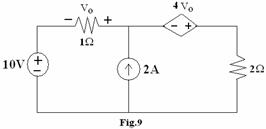
Thevenin’s theorem. Find the power loss in the 2![]() resistor shown in Fig. 9 using Thevenin’s theorem. (2+6)
resistor shown in Fig. 9 using Thevenin’s theorem. (2+6)
Q.5 a. Find
Z parameters of the network shown in the Fig.10. (8)

b. Derive
the expressions for O/P voltage, O/P current and amplification factor of single
tuned circuit shown in Fig. 11 at resonance. (8)
Q.6 a. Show that an
average power consumed by inductor circuit is Zero. (4)
b. Find the resultant of three currents ![]() and express it in the form
and express it in the form
of (6)

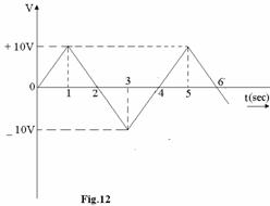
c.
Determine the form factor of the given
waveform (Fig.12). (6)
Q.7 a. Diagnose
whether the following impedance function represents a RL or RC network and find
its first Cauer Form Z(s)= [(s+4)(s+6) / (s+3)(s+5)] (8)
b. Test whether the polynomial ![]() is Hurwitz or not. (4)
is Hurwitz or not. (4)
c. Check the
positive realness of the function![]() (4) (iii)
Calculate the voltages across the capacitor and the coil. (8)
(4) (iii)
Calculate the voltages across the capacitor and the coil. (8)
Q.8 a. Design
a constant K-low pass filter having fc=2 kHz and design impedance Ro=600![]() . Obtain the value of attenuation at 4 kHz. (8)
. Obtain the value of attenuation at 4 kHz. (8)
b. Find the short-circuit admittance function![]() and
and ![]() for the network in the Fig.13. (8)
for the network in the Fig.13. (8)
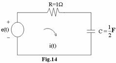
Q.9 a. Find the current i(t) for the network shown in
Fig.14, when the voltage source
is![]() (8)
(8)
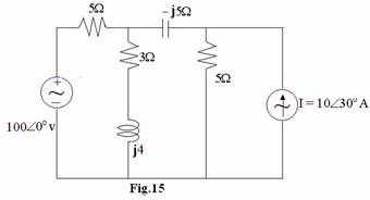
b. Find the current through the capacitor of (![]() 5)
5) ![]() reactance shown in Fig.15 below, using superposition theorem. (8)
reactance shown in Fig.15 below, using superposition theorem. (8)