Code: A-08 Subject: CIRCUIT THEORY & DESIGN
Time: 3 Hours June 2006 Max. Marks: 100
NOTE: There are 9 Questions in all.
· Question 1 is compulsory and carries 20 marks. Answer to Q. 1. must be written in the space provided for it in the answer book supplied and nowhere else.
· Out of the remaining EIGHT Questions answer any FIVE Questions. Each question carries 16 marks.
· Any required data not explicitly given, may be suitably assumed and stated.
Q.1 Choose the correct or best alternative in the following: (2x10)
a. Superposition theorem is applicable only to networks that are:
(A) linear. (B) nonlinear.
(C) time-invariant. (D) passive.
b. In the solution of network differential equations, the constants in the complementary function have to be evaluated from the initial conditions, and then the particular integral is to be added. This procedure is
(A) correct.
(B) incorrect.
(C) the one to be followed for finding the natural response.
(D) the one to be followed for finding the natural and forced responses.
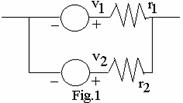
c. Two voltage sources connected in
parallel, as shown in the Fig.1, must satisfy the conditions:
(A)
![]() but
but ![]() . (B)
. (B)
![]() ,
, ![]() .
.
(C) ![]() . (D)
. (D) ![]() or
or ![]() if
if
![]()
d. The rms value of
the a-c voltage ![]() is:
is:
(A) 200 V. (B) 314 V.
(C) 157.23 V. (D) 141.42 V.
e. In a 2-terminal network containing at least one inductor and one capacitor, resonance condition exists only when the input impedance of the network is:
(A) purely resistive. (B) purely reactive.
(C) finite. (D) infinite.
f. If a network function has zeros only in the left-half of the s-plane, then it is said to be
(A) a stable function. (B) a non-minimum phase function.
(C) a minimum phase function. (D) an all-pass function.
g. Zeros in the right half of the s-plane are possible only for
(A) d.p. impedance functions. (B) d.p. admittance functions.
(C) d.p. impedance as well as (D) transfer functions.
admittance functions.
h. The natural response of a network is of the form ![]() . The network
must have repeated poles at s = 1 with multiplicity
. The network
must have repeated poles at s = 1 with multiplicity
(A) 5 (B) 4
(C) 3 (D) 2
i. The mutual
inductance M associated with the two coupled inductances ![]() is related to the
coefficient of coupling K as follows:
is related to the
coefficient of coupling K as follows:
(A)
![]() (B)
(B)
![]()
(C) ![]() (D)
(D)
![]()
j. An L-C impedance or admittance function:
(A) has simple poles and zeros in the left half of the s-plane.
(B) has no zero or pole at the origin or infinity.
(C) is an odd rational function.
(D) has all poles on the negative real axis of the s-plane.
Answer any FIVE Questions out of EIGHT Questions.
Each question carries 16 marks.
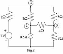
Q.2 a. Using
nodal analysis, find the power dissipated in the ![]() resistor of the network shown in
Fig.2. (8)
resistor of the network shown in
Fig.2. (8)
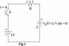
b. The
switch ![]() in
the circuit shown in Fig.3 is closed at t = 0. Obtain an expression for
in
the circuit shown in Fig.3 is closed at t = 0. Obtain an expression for ![]() , t > 0. (8)
, t > 0. (8)
Q.3 a. A
sinusoidal excitation ![]() is given to a network defined by the
input [x(t)] – output [y(t)] relation:
is given to a network defined by the
input [x(t)] – output [y(t)] relation: ![]() . Determine the spectrum of the
output. (8)
. Determine the spectrum of the
output. (8)
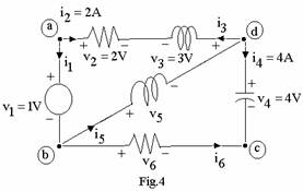
b. Using
Kirchhoff’s laws to the network shown in Fig.4, determine the values of ![]() and
and ![]() . Verify that the
network satisfies Tellegen’s theorem. (8)
. Verify that the
network satisfies Tellegen’s theorem. (8)
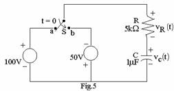
Q.4 a. Allowing
transients to die out with switch S in position ‘a’, the switch is then moved
to position ‘b’ at t=0, as shown in Fig.5. Find expressions for ![]() and
and ![]() for t > 0. (8)
for t > 0. (8)
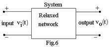
b. The only information known about the system in the black-box in Fig.6 is that:
(i) it is an initially relaxed linear system,
(ii)
when ![]() , output is
, output is ![]() .
.
Determine
the system excitation ![]() required to produce a
required to produce a
response ![]() . (8)
. (8)
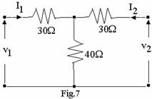
Q.5 a. For the symmetrical 2-port network shown in Fig.7, find the z-and ABCD-parameters. (8)
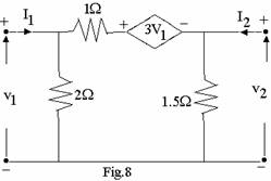
b. Determine the y-parameters for the network shown in Fig.8. (8)
Q.6 a. Given the network function ![]() , plot the zero and poles on
s-plane. Obtain the amplitude and phase for
, plot the zero and poles on
s-plane. Obtain the amplitude and phase for ![]() from the plot. (8)
from the plot. (8)
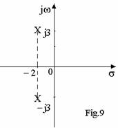
b. The pole configuration shown in Fig.9 refers to the system function H(s) of a single-tuned circuit. Construct the peaking circle and show the locations of the half power frequencies. (8)
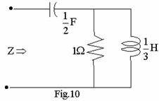
Q.7 a. Find
the driving-point impedance ![]() , for the network shown in Fig.10.
Verify that Z(s) is positive real and that the polynomial D(s) +
K.N(s) is Hurwitz. (8)
, for the network shown in Fig.10.
Verify that Z(s) is positive real and that the polynomial D(s) +
K.N(s) is Hurwitz. (8)
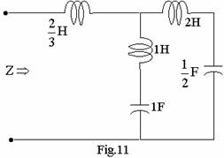
b. Design a one-port L-C circuit that contains only two elements and has the same driving-point impedance as that of the network shown in Fig.11. (8)
Q.8 a. Synthesise
the voltage-ratio ![]() using constant-resistance bridged-T
circuits. (8)
using constant-resistance bridged-T
circuits. (8)
b. Design
a one-port RL network to realize the driving point function ![]() . (8)
. (8)
Q.9 a. Synthesise
the network that has a transfer admittance ![]() and a
and a ![]() termination at the output end. (8)
termination at the output end. (8)
b. Obtain the system
function H(s) for a low-pass filter exhibiting Chebyshev characteristics with
1dB ripple in the passband ![]() and no less than 40 dB attenuation in
the stopband starting at
and no less than 40 dB attenuation in
the stopband starting at ![]() . (8)
. (8)