DipIETE
– ET (OLD SCHEME)
Code: DE15 Subject: CONTROL ENGINEERING
 Time: 3 Hours
Max. Marks: 100
Time: 3 Hours
Max. Marks: 100
NOTE: There are 9 Questions in all.
· Question 1 is compulsory and
carries 20 marks. Answer to Q.1 must be written in the space provided for it in
the answer book supplied and nowhere else.
· Out of the remaining EIGHT
Questions answer any FIVE Questions. Each question carries 16 marks.
· Any required data not explicitly
given, may be suitably assumed and stated.
Q.1 Choose
the correct or the best alternative in the following: (2 ![]() 10)
10)
a. Marginally stable systems
(A) Are
also classed as unstable system
(B) Have
one of the pole lying in R.H.S. of s-plane
(C) Equal
numbers of zeros and poles
(D) none of the
above
b. The transfer function of a system is![]() , the corner frequencies are
, the corner frequencies are
(A) 0.1
and 0.01 (B) 10 and 100
(C) 0.1
and 0.01 and 1000 (D) none of these
c. The maximum phase shift that can be provided by
a lead compensator with the transfer function ![]() is:
is:
(A) 15o (B) 30o
(C) 45o (D) 60o
d. The mechanical system is given in Fig.1
below:
The equation for mass M is:
(A) ![]()
(B) ![]()
(C) ![]()
(D) ![]()
e. The first two rows of Routh’s tabulation of a
fourth-order system are
|
s4 |
1 |
10 |
5 |
|
s3 |
2 |
20 |
|
The number of roots
of the system lying on the right half of the s-plane is
(A) 0 (B)
2
(C)
3 (D)
4
f. For a second-order system with the closed-loop transfer![]() , the settling time for 2% band in seconds, is
, the settling time for 2% band in seconds, is
(A) 1.5 (B) 2.0
(C) 3.0 (D) 4.0
g. Which of the following will not decrease as a
result of negative feedback?
(A) Instability (B) Bandwidth
(C) Overall
gain (D) Distortion
h. The Bode plot of the transfer function G(s) =
s, is
(A) Zero magnitude and zero phase shift
(B) Constant magnitude and constant phase
shift
(C) 6dB/octave and phase shift π/2
(D) -6dB/octave
and phase shift π/2
i. The open loop transfer function of unity
feedback control system is given by ![]() , if the gain K is
increased to infinity, then the damping ratio will tend to become
, if the gain K is
increased to infinity, then the damping ratio will tend to become
(A) ![]() (B) 1
(B) 1
(C) 0 (D) ¥
j. A root locus of a unity feedback system is shown
in the given Fig. 2. The open loop transfer function of the system is
(A) ![]() (B)
(B)
![]()
Fig.2
(C)
![]() (D)
(D)
![]()
Answer any FIVE Questions out
of EIGHT Questions.
Each
question carries 16 marks.
Q.2 a.
Distinguish
between
(i)
Open loop control system and closed loop control system
(ii) Transfer
function model and state space model (6)
b. Obtain
the transfer function ![]() for the given
mechanical system in Fig. 3:
for the given
mechanical system in Fig. 3:
Fig.3
(10)
Q.3 a. Obtain
the transfer function ![]() for the multi loop
control system shown in Fig. 4 below. (8)
for the multi loop
control system shown in Fig. 4 below. (8)
![]()
Fig.4
b. Draw
a signal flow graph for the following set of equations: (8)
y2 = a y1
– g y3
y3 = e y2
+ c y4
y4 = b y2
– d y4
Hence find the gains ![]() and
and ![]()
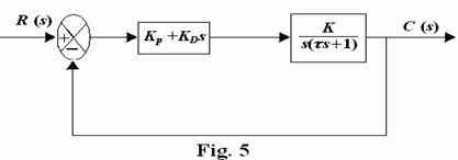
Q.4 a. A
second order control system with proportional derivative controller is shown in
the Fig. 5. Derive the expressions for it’s: (8)
(i) Steady state
error to step input
(ii) Natural frequency of oscillation
(iii) Damping
frequency of oscillation
b. Explain the following properties of the
feedback control system: (8)
(i) Disturbance rejection
(ii)
Insensitivity and robustness
Q.5 a. Sketch the root
locus of the system having ![]() for
for ![]() (12)
(12)
b. Define
stability. Differentiate between absolute and relative stability. (4)
Q.6 a.
The
characteristic equation for a certain feedback control system is given by ![]() (10)
(10)
(i) Find
the range of K for stability
(ii) What
is the frequency in rad/sec at which the system will oscillate?
(iii) How many roots of the characteristic
equation lie in the right half of the s-plane
for K = 5?
b. List the performance specifications used in time domain. (6)
Q.7 a. Sketch the Nyquist plot for a system with
![]() . Comment on close loop stability by using Nyquist stability
criterion. (10)
. Comment on close loop stability by using Nyquist stability
criterion. (10)
b.
Consider the feedback control system shown in
Fig. 6 below. Find the value
of ‘K’ and ‘a’
to satisfy the Following specifications Mr=1.25
and
![]() =12.65
rad / sec. . (6)
=12.65
rad / sec. . (6)
Fig.6
Q.8 a. Write
short notes on different type of compensation techniques. (10)
b. Explain
Phase margin and gain margin. How these can be obtained from Bode plots? (6)
Q.9 a. Explain
use of passive electric network for implementation of lag, lead and lag-lead compensators.
(8)
b. Obtain the transfer function model for armature controlled DC motor. (8)