AMIETE – ET (NEW SCHEME) – Code: AE61
Subject: CONTROL ENGINEERING
 Time: 3 Hours
Max. Marks: 100
Time: 3 Hours
Max. Marks: 100
NOTE: There are 9 Questions in all.
· Question 1 is compulsory and
carries 20 marks. Answer to Q. 1 must be written in the space provided for it
in the answer book supplied and nowhere else.
· Out of the remaining EIGHT
Questions answer any FIVE Questions. Each question carries 16 marks.
· Any required data not
explicitly given, may be suitably assumed and stated.
Q.1 Choose
the correct or the best alternative in the following: (2![]() 10)
10)
a. Transfer function of a control
system is known as
(A)
(B)
(C)
(D) None of the above
b.
The impulse response of the system is![]() , then the transfer function of the system
, then the transfer function of the system
(A) ![]() (B)
(B) ![]()
(C) ![]() (D)
(D) ![]()
c. The position
control is
(A) an automatic regulating system (B)
a process control system
(C) a servo mechanism (D) none of the above
d. For the signal flow graph shown in Fig.1, the
overall transfer function ![]() of the system is
of the system is
(A) G
(B)

![]()
(C) ![]()
(D) ![]()
e. Routh’s array is given by
![]() 1 9
23 15
1 9
23 15
![]() 3 18 15
3 18 15
![]() 3 18 15
3 18 15
![]() 0 0
0 0
The auxiliary equation of this array is
(A) ![]() (B)
(B) ![]()
(C) ![]() (D)
(D) ![]()
f. The open loop gain for a unity feedback
system is![]() . The steady state
velocity error is
. The steady state
velocity error is
(A) 0 (B) ![]()
(C) 1 (D) 12
g.
The proportional error device has output
as function of
(A) derivative of error (B) integral of error
(C) error (D) error and integral of error
h. Gain crossover frequency is
one at which ![]() is
is
(A) Equal to 1 (B)
equal to -1
(C) >1 (D) <
-1
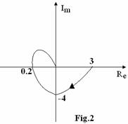
i. The
polar plot of a system shown
in Fig.2.
The gain margin in dB is
(A) 18.06
(B) 15.56
(C) 13.97
(D) 20.00
j. The transfer function of a RC network is![]() . The required
condition to act as phase lead is
. The required
condition to act as phase lead is
(A)
![]() (B)
(B) ![]()
(C) ![]() (D)
(D) ![]()
Answer any FIVE Questions out
of EIGHT Questions.
Each question carries 16
marks.
Q.2 a. Obtain the transfer function of a field controlled
DC motor. (8)
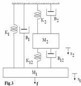
b. For the mechanical system shown in
Fig.3
(i) Draw
the mechanical network.
(ii) Write
the performance equations. (8)
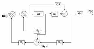
Q.3 a. For the block diagram shown in Fig.4, obtain
the transfer function using block diagram reduction rules. (8)
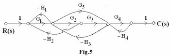
b. Obtain the transfer function of the signal flow graph shown
in Fig.5, using Mason’s gain formula. (8)
Q.4 a. Explain
the effect of feedback on system dynamics and bandwidth. (10)
b. With neat
diagram explain the working of Stepper motor. (6)
Q.5 a. Determine the time response specifications
for a unit step input to a unity feedback system having the open loop gain![]() . (8)
. (8)
b.
A unity feedback control system is
characterised by the loop transfer function
![]() . Find the range of K
for which the system is stable using Routh Hurwitz Criteria. (8)
. Find the range of K
for which the system is stable using Routh Hurwitz Criteria. (8)
Q.6 a. Write
the rules to construct root locus of a control system. (8)
b. The
OLTF is given by![]() . Show that the
complex part of the root locus is circle. (8)
. Show that the
complex part of the root locus is circle. (8)
Q.7
a. Derive the expression for bandwidth of second order system. (6)
b. Sketch the Bode plot for a control system
having OLTF as![]() . Also find GM and PM. (10)
. Also find GM and PM. (10)
Q.8 a. A
unity feedback control system has open loop transfer function ![]() . Design a PI
controller to meet the following specifications
. Design a PI
controller to meet the following specifications
(i) ![]() (ii)
(ii) ![]() (10)
(10)
b. Draw the circuit diagram of lead/lag
compensator using op-amp. Derive the
expression for compensator transfer function. (6)
Q.9
a. A feedback system has a closed loop transfer function![]() . Construct canonical
state model for this system and give the block diagram representation. (8)
. Construct canonical
state model for this system and give the block diagram representation. (8)
b. A linear time
invariant system is represented by the following state equation
 . Compute the solution
of the equation, assuming the initial state vector
. Compute the solution
of the equation, assuming the initial state vector![]() . (8)
. (8)