AMIETE – ET (NEW SCHEME) – Code: AE59
Subject: CIRCUIT THEORY & DESIGN
 Time: 3 Hours
Max. Marks: 100
Time: 3 Hours
Max. Marks: 100
NOTE: There are 9 Questions in all.
· Question 1 is compulsory and
carries 20 marks. Answer to Q.1 must be written in the space provided for it in
the answer book supplied and nowhere else.
· Out of the remaining EIGHT
Questions answer any FIVE Questions. Each question carries 16 marks.
· Any required data not
explicitly given, may be suitably assumed and stated.
Q.1 Choose
the correct or the best alternative in the following: (2![]() 10)
10)
a. The internal resistance of an ideal current source
is
(A) infinity (B) zero
(C) 1M![]() (D) 10
(D) 10![]()
b. The number of chords present in a graph having ‘n’ number of nodes and ‘b’ number of branches is
(A) n-1 (B) n+1
(C) (b-1) (D) b-(n-1)
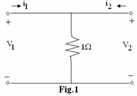
c. The T-parameters of given network in Fig.1
(A) ![]() (B)
(B) ![]()
(C)
![]() (D)
(D)
![]()
d. Voltage drop
across an inductor is
(A) Li (B) ![]()
(C) ![]() (D)
(D) ![]()
e. The Q factor of
a series RLC circuit is
(A) ![]() (B)
(B) ![]()
(C) ![]() (D)
(D) ![]()
f. The impedance
of a branch consisting of ![]() resistor and 2H
inductor in series is
resistor and 2H
inductor in series is
(A) ![]() (B)
(B) ![]()
(C) ![]() (D)
(D) ![]()
g.
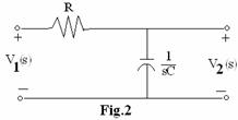
![]() of the network given in
Fig.2 is
of the network given in
Fig.2 is
(A) ![]() (B)
(B) ![]()
(C)  (D)
(D) 
h. The defining
equations of ‘h’ parameter for describing two port network are
(A) ![]() (B)
(B) ![]()
(C) ![]() (D)
(D) ![]()
i. At each pole the network function becomes
(A) zero (B) one
(C) infinite (D) finite
j. Laplace
inverse of a function ![]() is
is
(A) ![]() (B)
(B) ![]()
(C) ![]() (D)
(D) ![]()
Answer any FIVE Questions out
of EIGHT Questions.
Each question carries 16
marks.
Q.2 a. Draw the equivalent circuit of practical
voltage source and current source. Also
explain their terminal v – i characteristics. (6)
b. In
the network shown in Fig.3 all sources are time invariant. Determine the
numerical value of
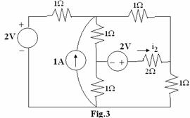
![]() . (10)
. (10)
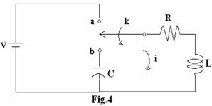
Q.3 a. In
the network shown in Fig.4, switch ‘k’ is changed from position a to b at t = 0.
Solve for i, ![]() and
and ![]() at
at ![]() , if
, if ![]() , L = 1H,
, L = 1H,![]() and V = 100 volts. (8)
and V = 100 volts. (8)
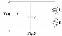
b. The circuit shown in Fig.5 is a shunt peaking
circuit. Show that the admittance Y(s)
is of the form![]() . Express
. Express ![]() in terms of R, L and
C. (8)
in terms of R, L and
C. (8)
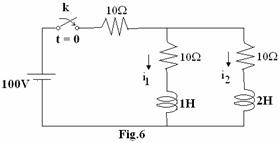
Q.4 a. In the network shown in Fig.6, the switch k
is closed at t = 0 with the network previously
unenergized. Find ![]() and
and ![]() , using
Laplace transform method.
(8)
, using
Laplace transform method.
(8)
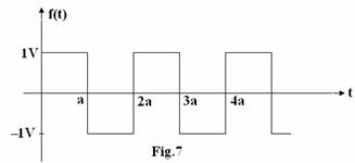
b. Find the
Laplace transform of the function f(t) shown in Fig.7. (8)
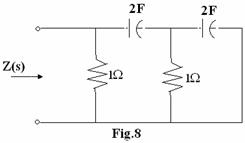
Q.5 a. For the RC network shown in Fig.8, find the
transform impedance Z(s) and express it
in factored form. (6)
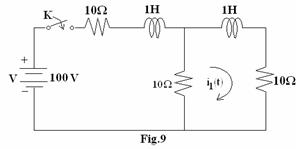
b. Find ![]() in the network shown
in Fig.9 using thevenin theorem, Switch K is closed at t = 0. (10)
in the network shown
in Fig.9 using thevenin theorem, Switch K is closed at t = 0. (10)
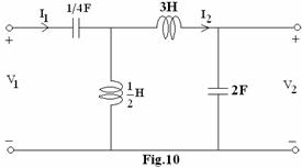
Q.6 a. Find
the voltage transfer function ![]() & input impedance
& input impedance ![]() for the network shown
in Fig.10. (8)
for the network shown
in Fig.10. (8)
b. Test whether the given polynomial ![]() is Hurwitz or not? (8)
is Hurwitz or not? (8)
Q.7 a. Obtain expressions for ‘h’ parameter in terms of Z and Y parameters (8)
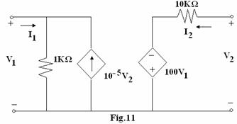
b. Find Z parameters for the two port network
shown in Fig.11. (8)
Q.8 a. Determine
the Foster first form after synthesizing the RL driving point impedance
function ![]() . (8)
. (8)
b. Synthesize the
Cauer first form of LC driving point impedance function  . (8)
. (8)
Q.9 a. Synthesize the positive real function  . (9)
. (9)
b. Write a note
on comparison of maximally flat and Chebyshev approximation in terms of low pass
filter design. (7)