AMIETE – ET (OLD SCHEME)
 Code: AE26 Subject:
POWER ELECTRONICS
Code: AE26 Subject:
POWER ELECTRONICS
Time: 3 Hours Max. Marks: 100
NOTE: There are 9 Questions in all.
· Question 1 is compulsory and
carries 20 marks. Answer to Q. 1must be written in the space provided for it in
the answer book supplied and nowhere else.
· Out of the remaining EIGHT
Questions answer any FIVE Questions. Each question carries 16 marks.
· Any required data not explicitly
given, may be suitably assumed and stated.
Q.1 Choose
the correct or the best alternative in the following: (2x10)
a. In an SCR circuit, the angle
of conduction can be changed by changing
(A) anode voltage (B)
anode current
(C) forward
current rating (D) gate current
b. Circuit symbol for IGBT is
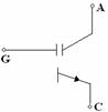

(A) (B)
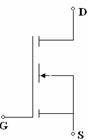

(C) (D)
c. If the chopper switching frequency is 200 Hz
and ![]() time is 3 ms, the duty
cycle is
time is 3 ms, the duty
cycle is
(A)
0.4 (B) 0.8
(C) 0.6 (D) 0.75
d. In a three phase half-wave rectifier, the peak inverse voltage equals.
(A)
![]() (B)
(B) ![]()
(C) (2)E (D) ![]()
E =
RMS voltage of secondary.
e. A freewheeling diode is sometimes connected in an inductive load circuit. Its purpose in a half wave rectifier circuit is
(A) to conduct during the negative
half of supply.
(B) to give better filtering and
reduce ripple.
(C) to conduct so as to reduce the angle of conduction to ![]() .
.
(D) to improve transformer utilisation.
f. A UJT is used for triggering an SCR has the
supply voltage ![]() . The intrinsic
standoff ratio = 0.75. The UJT will
conduct when the biased voltage
. The intrinsic
standoff ratio = 0.75. The UJT will
conduct when the biased voltage ![]() is
is
(A) 25 V (B) ![]()
(C) 33.3V (D) ![]()
g. When a line commutated converter operates in the inverter mode, it
(A) draw
both reactive and real power from the ac supply.
(B)
delivers both real and reactive power to the ac supply.
(C) delivers real power to the ac supply.
(D) draws reactive power from ac supply.
h. When a series LC circuit is connected to a dc supply of V volts through a thyristor, then the peak current through thyristor is
(A) ![]() (B)
(B) ![]()
(C) ![]() (D)
(D)
![]()
i. In a current source inverter, if frequency of the output voltage is f Hz, then frequency of the voltage input to CSI is
(A) f (B) 2f
(C) ![]() (D) 3f
(D) 3f
j. A 3-phase to 3-phase cyclo converter requires
(A) 18 SCR’s for 3-pulse device (B) 18 SCR’s for 6-pulse device
(C) 36 SCR’s for 3-pulse device (D) 36 SCR’s for 6-pulse
device
Answer any FIVE Questions out of EIGHT
Questions.
Each
question carries 16 marks.
Q.2 a. Discuss the construction and static V-I
characteristics of an SCR. Show latching
current and holding current on its V-I characteristics. (8)
b. Determine the
values of ![]() inductance and snubber circuit parameters
inductance and snubber circuit parameters ![]() and
and ![]() for the circuit shown
in Fig.1. The supply voltage is 300 V
dc, load resistance
for the circuit shown
in Fig.1. The supply voltage is 300 V
dc, load resistance ![]() and repetitive peak
current is
and repetitive peak
current is ![]() . The specified limit
for
. The specified limit
for ![]() and
and ![]() for the SCR are 25
for the SCR are 25 ![]() and 250
and 250![]() respectively. Take
damping factor
respectively. Take
damping factor ![]() to be about 0.72 for
optimum solution.
(8)
to be about 0.72 for
optimum solution.
(8)

Q.3 a. Draw the waveforms for the average load
voltage and load current for an RL load fed from a single phase supply through
a thyristor. Also derive the expression
for load current. (8)
b. Fig.2 shows a battery charging circuit using
SCR’s. Derive the expression and find
the value for average current flowing through the battery if the voltage from
neutral to any line is 230V (rms) and firing angle for thyristor is
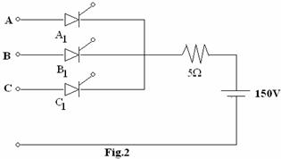
![]() . (8)
. (8)
Q.4 a. A step down dc chopper
with an input voltage of 220 V has a resistive load of R=15![]() , a chopping frequency of 1 KHz and a duty cycle of 50%. If the voltage drop at chopper, when the
chopper switch remains on is 4 V determine
, a chopping frequency of 1 KHz and a duty cycle of 50%. If the voltage drop at chopper, when the
chopper switch remains on is 4 V determine
(i) The average output
voltage and rms voltage
(ii) The effective input resistance Ri of the chopper and chopper
efficiency. (8)
b. What is a buck regulator? Write its advantage and disadvantages. (8)
Q.5 a. Explain the need of commutation in thyristor circuits. What are the different methods of commutation schemes? (8)
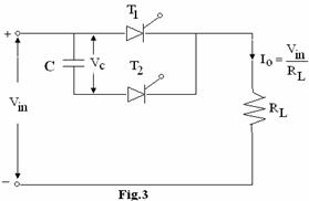
b. Determine the available turn off time for the impulse commutated
thyristor circuit as shown in Fig.3, if ![]() ,
, ![]() and
and ![]() .
(8)
.
(8)
Q.6 a. A single phase voltage controller has
input voltage 220V, 50 Hz and a load of ![]() . For 6 cycles on and
4 cycles off determine
. For 6 cycles on and
4 cycles off determine
(i) input power factor and rms output voltage.
(ii) average and rms thyristor current. (8)
b. Discuss the principle of ON-OFF control and
phase control for power transfer. (8)
Q.7 a. What is a cyclo converter? List some of its industrial applications. (8)
b. Show that the fundamental rms value of per
phase output voltage of low frequency for an m-phase half wave cyclo converter
is given by
![]() where
where ![]() =rms value of supply voltage and firing angle
=rms value of supply voltage and firing angle ![]() is given as
is given as ![]() . (8)
. (8)
Q.8 a. A resistive load of ![]() is fed from a dc input
voltage
is fed from a dc input
voltage ![]() through a single phase half bridge and full bridge (one at a
time) inverter. Compare the output rms
voltage, rms output current at fundamental frequency, the output power and the
peak reverse blocking voltage for both the cases. (8)
through a single phase half bridge and full bridge (one at a
time) inverter. Compare the output rms
voltage, rms output current at fundamental frequency, the output power and the
peak reverse blocking voltage for both the cases. (8)
b. A three phase
bridge inverter delivers power to a resistive load from a 300 V dc source. For a star-connected load of 5![]() per phase, determine
per phase, determine
(a) rms
value of load-current. (ii) load power,
for both (i) ![]() mode and (ii)
mode and (ii)
![]() mode. (8)
mode. (8)
Q.9 a. The speed of a 15 HP, 220 V, 1000 rpm dc
series motor is controlled using a single-phase half controlled bridge
converter. The combined armature and
field resistance is 0.2 ohm. Assume
continuous and ripple free motor current and speed of 1000 rpm and K = 0.03 ![]() . Determine
. Determine
(i) motor current and (ii)
motor torque
For, a firing angle ![]() , AC voltage = 250 V. (8)
, AC voltage = 250 V. (8)
b. Discuss dc
circuit model of chopper controlled rotor circuit resistance of an induction
motor. (8)