AMIETE – ET (OLD SCHEME)
Code: AE12 Subject: INSTRUMENTATION AND MEASUREMENT
 Time: 3 Hours
Max. Marks: 100
Time: 3 Hours
Max. Marks: 100
NOTE: There are 9 Questions in all.
· Question 1 is compulsory and
carries 20 marks. Answer to Q. 1 must be written in the space provided for it
in the answer book supplied and nowhere else.
· Out of the remaining EIGHT
Questions answer any FIVE Questions. Each question carries 16 marks.
· Any required data not
explicitly given, may be suitably assumed and stated.
Q.1 Choose
the correct or the best alternative in the following: (2![]() 10)
10)
a. Example
of an active transducer is
(A)
strain gauge (B) LVDT
(C)
piezoelectric transducer (D) resistance transducer
b. In
an amplified dc meter, the role of the amplifier is to provide
(A) high gain (B) large
bandwidth
(C)
high input impedance (D)
low input impedance
c. The purpose of providing a varactor diode in
a signal generator is to facilitate
(A)
amplitude modulation (B)
tuning the main signal
(C)
frequency multiplication (D)
frequency modulation
d. For
horizontal deflection system of a CRO, the waveform of voltage to be applied
should be
(A)
rectangular (B)
ramp
(C)
impulse (D) sinusoidal
e. To
extend the frequency range of a frequency counter one may use
(A)
a prescalar which is a digital counter
(B)
an amplifier with suitable gain
(C)
a comparator with zero crossing detection
(D)
an amplifier with large bandwidth
f. Bolometer
measures RF power using
(A) magnetic field of RF
(B) heating effect of RF
(C) induced emf by RF field
(D) heterodyning with another RF
source
g. The receiver parameter ‘image’ refers to
(A)
reflection of RF from unmatched load
(B)
uncontrolled change in local oscillator frequency
(C) spurious response to heterodyning process
(D) shift of carrier frequency
h. The IF amplifier used in spectrum analyzer is
(A) a high gain large bandwidth amplifier
(B) successive limiting type logarithmic
amplifier
(C) a narrow band tuned amplifier
(D) a unity gain high input impedance
amplifier
i. An example of a magneto resistive material
is
(A) Quartz (B) Nichrome alloy
(C)
Bismuth (D) Mu-metal
j. The
input to an 8-bit A/D converter with 10 V reference is 3.797 volts. The digital output from the converter is
(A)
1000
0011 (B) 0110 0001
(C) 00110111 (D) 1001 1001
Answer any FIVE Questions out
of EIGHT Questions.
Each question carries 16
marks.
Q.2 a.
Distinguish between systematic and
random errors in measurement
systems.
State briefly the scientific approaches to minimize these errors. (10)
b. Define the term ‘settling time’ of an instrument and indicate the
factors determining its value in a system. (6)
Q.3
a. What are the advantages of using a chopper-stabilized amplifier in
voltage measurements? Describe using a
neat circuit diagram, the operation of a series-shunt chopper based on MOSFETs. (10)
b.
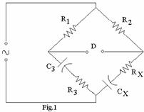
Find the values of ![]() and
and ![]() in the capacitance
comparison bridge shown in Fig.1 below which is balanced with the following
parameters.
in the capacitance
comparison bridge shown in Fig.1 below which is balanced with the following
parameters. ![]()
![]()
![]()
![]() . (6)
. (6)
Q.4 a. Why linearizing circuit is necessary in a
sweep frequency generator? Explain using
circuit diagram, the working of a linearizing circuit connected to a sweep
generator. (8)
b.
Draw block schematic of a frequency
counter and delineate its operation. (8) AB and BC
are non reactive resistor of 100Ω each, DA is standard variable inductor L
of resistance 32.7Ω and CD comprises a standard variable resistor R in
series with a coil of unknown impedance. Balance
Q.5 a. Derive an expression for deflection
sensitivity of a CRO with electrostatic deflection. (9)
b. What is
the difference between ‘dual-beam’ and ‘dual trace’ oscilloscopes? Show a scheme to derive dual trace for a CRO
and explain its operation. (7)
Q.6 a.
Draw a neat figure to illustrate an
experimental set-up to measure magnetic flux by measuring emf induced by the
flux. (10)
b.
Explain how RF power is measured by RF
volt-meter. (6)
Q.7 a.
Describe measurement set-up and
procedure to measure sensitivity of a radio receiver by Quieting method. (7)
b. Explain Harmonic distortion. What are the causes by which harmonic distortion may result? Show a block schematic of heterodyne harmonic analyzer and explain its operation. (9)
Q.8 a. Taking a minimum of 4 bits inputs, show any
one type of D/A converter and explain its operation. (8)
b. Draw a Hay’s bridge circuit and obtain expressions for unknown
inductance and resistance in one arm of the bridge. (8)
Q.9 a.
Discuss applications of capacitive
transducers for displacement measurement.
Show a scheme of capacitive transducer in a bridge by which outputs
proportional to linear displacements may
be obtained.
(10)
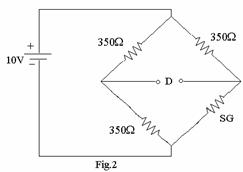
b. Find the bridge offset voltage in the strain gauge bridge shown in
Fig.2 when a strain of 1450![]() is applied on the SG, whose GF = 2.03 and nominal resistance
is 350
is applied on the SG, whose GF = 2.03 and nominal resistance
is 350![]() . The bridge is
balanced when the gauge is unstrained. (6)
. The bridge is
balanced when the gauge is unstrained. (6)