AMIETE – ET (OLD SCHEME)
 Code: AE11 Subject:
CONTROL ENGINEERING
Code: AE11 Subject:
CONTROL ENGINEERING
Time: 3 Hours Max. Marks: 100
NOTE: There are 9 Questions in all.
· Question 1 is compulsory and
carries 20 marks. Answer to Q. 1. must be written in the space provided for it
in the answer book supplied and nowhere else.
· Out of the remaining EIGHT
Questions answer any FIVE Questions. Each question carries 16 marks.
· Any required data not explicitly
given, may be suitably assumed and stated.
Q.1 Choose
the correct or the best alternative in the following: (2x10)
a. In a
closed-loop feedback control system,
(A)
input
can be manipulated to obtain the desired output of the system and can also be
made dependent on the actual output of the system
(B)
there is no need to manipulate the input to get
the desired output
(C) input doesn’t depends upon the actual output of
the system
(D) input can be manipulated to obtain the
desired output of the system, but cannot be made dependent on the actual output
of the system
b. If ![]() and f(t) as
and f(t) as ![]() is
is ![]() , then the value of k is
, then the value of k is
(A)
![]() (B)
1
(B)
1
(C) 2 (D)
¥
b. The sum of the gains of the feedback paths in the signal flow graph below is
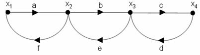
(A) af
+ be + cd + abef + bcde + abcdef
(B) af
+ be + cd + abef + bcde
(C) af + be + cd + abef + abcdef
(D) af + be + cd
d. The block diagram shown in the figure is equivalent to
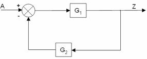
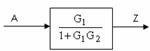
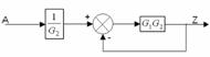
(A) (B)
(C) both (A)
& (B)
(D) None of these
e. The transfer function
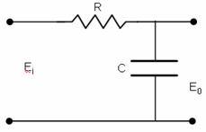
![]() of a series RC circuit shown in figure is
of a series RC circuit shown in figure is
(A)
![]()
(B)
![]()
(C) ![]()
(D) ![]()
f. Which of the following devices cannot be used as error detector?
(A) amplidyne (B) potentiometer
(C) synchros (D) LVDT
g. A first-order control system is given with transfer function as ![]() . Its unit-step response for
. Its unit-step response for ![]() is represented by
is represented by
(A) ![]() (B)
(B)
![]()
(C) ![]() (D)
None
of these
(D)
None
of these
h. The figure depicts a
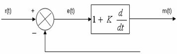
(A)
P-
control action
(B) P-D control action
(C) P-I control action
(D) P-I-D control
action
i. For the given open loop system determine the angles, which the
asymptotes make with the real axis, ![]()
(A) 00, 900, 1800,
2700 (B) 600, 1800, 3000
(C) 600, 1500, 2400,
3300 (D) 600,
1200, 2400, 3000
j. In reference to the frequency domain analysis of the linear control systems, the value of radius N-circles is given by
(A) ![]() (B)
(B)

(C)  (D)
(D) ![]()
Answer any FIVE Questions out
of EIGHT Questions.
Each
question carries 16 marks.
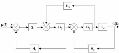
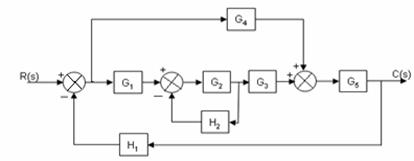
Q.2 a. Determine the closed loop transfer
function of the following system using block diagram reduction technique: (8)
b. Develop
the signal flow graph and determine the overall transfer function of the given
system using Mason’s Gain formula (8)
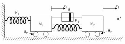
Q.3 a.
Write
down the differential equations describing the dynamics of the mechanical
system shown in the figure below. Draw the electrical analogous of both types for
the given system. K1 and
b. Explain the meaning of
proportional-plus-integral control action (PI). With the help of an example,
explain the function/s of a controller used in P-I control action. (8)
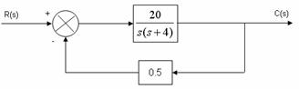
Q.4 a. For the system shown in the below figure
determine the sensitivity of the closed loop transfer function for w = 1 rad/sec
with respect to
(i) forward path transfer function (ii)
backward path transfer function (8)
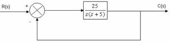
b. The figure below shows a unity feedback
second-order control system. Determine (a) natural frequency of oscillations,
(b) damping ratio, (c) damped frequency of oscillations, (d) rise time, (e)
percentage overshoot, (f) settling time with 5% criteria time, when the system
is subjected to a unit-step input. (8)
Q.5 a. How an armature controlled DC motor is used
in control system applications? Give a schematic diagram, derive the transfer
function and draw a block diagram for the system. (8)
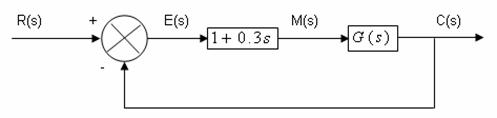
b. A unity feedback second order control
system using P-D controller has an effective damping ratio = 0.8. The transfer
function of the P-D controller is (1+0.3s) and the damping ratio of the control
system without P-D control is 0.2. Determine the overall transfer function of
the system without P-D controller. (8)
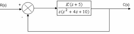
Q.6 a. Using the Routh-Hurwitz criterion determine
the restrictions on the value of parameter K for the system to be stable. The
system is represented in figure below: (8)
b. Determine the position, velocity and
acceleration error constants for a feedback system with the open loop transfer
as ![]() . (8)
. (8)
Q.7 a. A feedback control system has an
open-loop transfer function,![]() . Find the root-locus as K is varied from 0 to ¥. (10)
. Find the root-locus as K is varied from 0 to ¥. (10)
b. Discuss
using diagram, op-amp as compensation network. (6)
Q.8 a. Draw the asymptotic Bode plot for a
system whose open-loop sinusoidal transfer function is given as ![]() .
.
Determine
(i)
static
error coefficient (ii) gain margin
(iii) phase margin (iv) closed-loop stability (10)
b. Compare the
following Cascade Compensator. Use diagrams where ever applicable. (6)
(i) Cascade
Lead-Compensator, (ii) Cascade Lag-Compensator,
(iii) Cascade Lag-Lead Compensator.
Q.9 a. Using Nyquist criterion determine whether
the closed-loop system having the open-loop transfer function, ![]() is stable or not. (10)
is stable or not. (10)
b. Explain how
you can determine the various parameters of a closed-loop system from a
Nicholas Chart. (6)