AMIETE – ET (OLD SCHEME)
 Code: AE08 Subject:
CIRCUIT THEORY & DESIGN
Code: AE08 Subject:
CIRCUIT THEORY & DESIGN
Time: 3 Hours Max. Marks: 100
NOTE: There are 9 Questions in all.
· Question 1 is compulsory and
carries 20 marks. Answer to Q.1 must be written in the space provided for it in
the answer book supplied and nowhere else.
· Out of the remaining EIGHT
Questions answer any FIVE Questions. Each question carries 16 marks.
· Any required data not explicitly
given, may be suitably assumed and stated.
Q.1 Choose
the correct or the best alternative in the following: (2x10)
a.
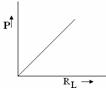
A
voltage source with an internal resistance
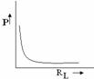
![]() , supplies power to a load
, supplies power to a load ![]() . The power P delivered
to the load varies with
. The power P delivered
to the load varies with ![]() as
as
(A)
(B)
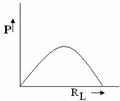
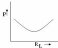
(C) (D)
b.
A series circuit has an
impedance ![]() , its susceptance is
, its susceptance is
(A)
![]() (B)
(B) ![]()
(C) ![]() (D)
(D) ![]()
c.
If A is the incidence matrix of
![]() and B be the loop
matrix of network
and B be the loop
matrix of network ![]() , the condition for the two networks to be duals of each
other is that
, the condition for the two networks to be duals of each
other is that
(A) rank of [A] > rank of [B] (B) rank of [A] < rank of [B]
(C) rank of [A] = rank of [B] (D) None of these
d. In the initially relaxed circuit shown in
Fig.1, the switch S is closed at t=0.
The value of current at t=0+ will be
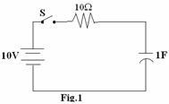
(A)
zero
(B)
-1A
(C) +1A
(D) 100A
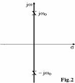
e. The closed-loop pole location of
a network is shown in Fig.2.
The nature of the unit step response
would be
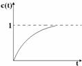
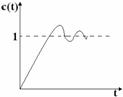
(A) (B)
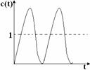
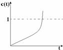
(C) (D)
f. In a given circuit the input voltage and current are given by

The
power consumed in the circuit is
(A) 100 watts (B) 50 watts
(C) 25 watts (D) 12.5 watts
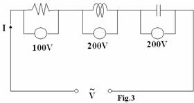
g. The voltmeter readings across different circuit elements are as shown in the Fig.3. The reactive component of the current I in the circuit is
(A) 10A (B)5A
(C) zero (D) 2A
h. For the two port network shown in Fig.4, select the correct statement
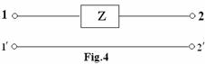
(A) It does not have z-parameter (B)
It has z-parameters
(C) It does not have y-parameters (D)
It does not have ABCD parameters
i. A network whose impedance function is  is synthesized. It consists of ‘n’ LC tank circuits in series
with an inductance and/or a capacitance.
The value of ‘n’ is
is synthesized. It consists of ‘n’ LC tank circuits in series
with an inductance and/or a capacitance.
The value of ‘n’ is
(A) zero (B)
1
(C) 2 (D) 3
j. The driving-point impedance of an RC network
is given by ![]() . Its canonical
realization will have
. Its canonical
realization will have
(A) 6 elements (B)
5 elements
(C) 4 elements (D) 3 elements
Answer
any FIVE Questions out of EIGHT Questions.
Each
question carries 16 marks.
Q.2 a. State and explain the terminal relationships
for ideal R, L and C in reference to network analysis. (6)
b. Define
positive real function and write its properties. (10)
Q.3 a. Explain the concepts of duality in reference
to electrical networks. Explain the
graphical procedure of constructing the dual of a network. (8)
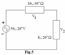
b. Find the voltages across the impedances in
circuit shown in Fig.5. Transform the
voltage source and ![]() impedance to a Norton’s
equivalent current source and again find the voltages. Compare results. (8)
impedance to a Norton’s
equivalent current source and again find the voltages. Compare results. (8)
Q.4 a. State and illustrate with the help of an
example the final value theorem in reference to electric networks. (6)
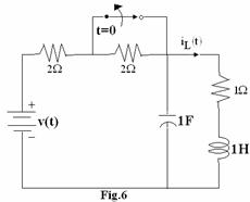
b. In the network shown in Fig.6, the switch is
initially closed for a long time. The
switch is opened at t=0. Find
differential equation relating ![]() and its derivatives with
and its derivatives with
![]() and also evaluate the initial
conditions required to solve for
and also evaluate the initial
conditions required to solve for ![]() . (10)
. (10)
Q.5 a. State
super-position theorem in reference to electrical networks and also give its
limitations. (7)
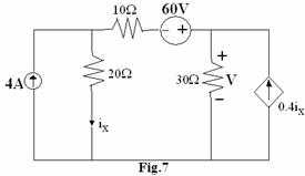
b. Use super-position theorem to find voltage V
in the network shown in Fig.7. (9)
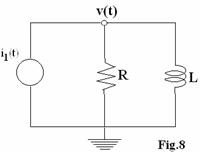
Q.6 a. The network shown in
Fig.8 has a sinusoidal excitation ![]() . Determine the
response node-to-datum voltage v(t) in the steady state. (8)
. Determine the
response node-to-datum voltage v(t) in the steady state. (8)
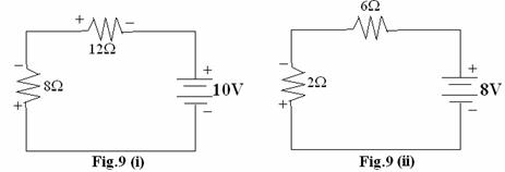
b. The networks shown in
Fig.9 (i) & Fig.9 (ii) have the identical graphs. Verify Tellegen’s theorem for these networks. (8)
Q.7 a. Write
the properties of
(i) L-C imittance functions.
(ii) R-C
impedance functions.
(iii) R-L impedance functions. (8)
b. (i) A
coil having a 2![]() resistance is connected in series with a
resistance is connected in series with a ![]() capacitor. The circuit resonates at 100 Hz. What is the inductance of the coil?
capacitor. The circuit resonates at 100 Hz. What is the inductance of the coil?
(ii) If the
circuit is connected across a 100 V, 100 Hz ac source, find the power
dissipated in the coil.
(iii) Calculate the voltages across the capacitor
and the coil. (8)
Q.8 a. Show
that when two 2-port networks ![]() and
and ![]() are connected in
parallel, the equivalent Y-parameters of the combined network is the sum of
Y-parameters of each individual 2-port network. (7)
are connected in
parallel, the equivalent Y-parameters of the combined network is the sum of
Y-parameters of each individual 2-port network. (7)
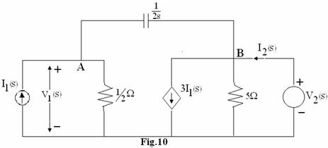
b. Determine the h-parameters of the network
shown in Fig.10. (9)
Q.9 Write
notes on any TWO of the
following:
(i)
Properties of transfer function.
(ii)
Chebyshev approximation.
(iii)
Magnitude and frequency scaling. (16)