DipIETE – ET (OLD SCHEME)


Flowchart: Alternate Process: JUNE 2009Code: DE15                                                                       Subject: CONTROL ENGINEERING

Time: 3 Hours                                                                                                     Max. Marks: 100


NOTE: There are 9 Questions in all.

·      Question 1 is compulsory and carries 20 marks. Answer to Q. 1. must be written in the space provided for it in the answer book supplied and nowhere else.

·      Out of the remaining EIGHT Questions answer any FIVE Questions. Each question carries 16 marks.

·      Any required data not explicitly given, may be suitably assumed and stated.


Q.1       Choose the correct or the best alternative in the following:                                 (2 10)


a.   In terms of Bode plot, the system is stable if


      (A) PM = GM                                    (B) PM and GM, both positive

      (C) PM and GM, both negative           (D) PM negative but GM positive


b.   The lag compensation in control system is achieved by


      (A) Adding zeros in the transfer function                                                                                       

      (B) adding poles in the transfer function

      (C) Both (A) and (B)                                                                                                                               

      (D) none of these                                                                                                            


c.   Consider the function  where  is laplace transform of .   is equal to


      (A) 5/2                                               (B) one

      (C) zero                                              (D) none of the above


d.   As compared to closed loop system, an open loop system is :


      (A) More stable as well as more accurate                                                                                     

      (B) less stable as well as less accurate

      (C) More stable but less accurate                                                                                                 

      (D) less stable but more accurate


e.   The eigen value of the matrix


      (A)  –1, –2, –3                                   (B)  0, –3, –4

      (C)  0, 0, –4                                       (D)  None of the above


f.    In the control system shown in Fig 1, the controller which can give zero steady state error to a ramp input, with K=9 is

Text Box:

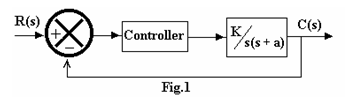
      (A) proportional type                         

      (B) integral type

      (C) derivative type                             

      (D) proportional plus

            derivative type


g.   The output response of a linear system is the system transfer function when the input is:


      (A) a step signal                                  (B) a ramp signal

      (C) an impulse signal                           (D) a sinusoidal signal


h.   When the signal flow graph is shown in the Fig.2, the overall transfer function will be
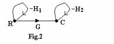


      (A)                                         (B)

      (C)                  (D)


i.    For the critically damped condition, the damping ratio is


      (A) Zero                                             (B) equal to one

      (C) Any value greater than one            (D) any value less than one


j.    In position control system, the device used for providing rate feedback voltage is called


      (A) Potentiometer                               (B) synchro-transmitter

      (C) synchro-receiver                           (D) tachogenerator


Answer any FIVE Questions out of EIGHT Questions.

Each question carries 16 marks.


  Q.2     a.   Distinguish between the following:                                                                       (6)

                   (i)   Static and Dynamic system                   (ii)  Closed loop and Open loop system

 
                   (iii) Linear and non-linear system


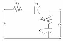
             b.   Use force voltage analogy and give equivalent mechanical network for the electrical network given below:                                               (10)


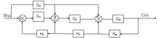
  Q.3     a.   Figure given below is a block diagram of a linear feedback system. Obtain a signal flow graph for the system and hence obtain overall gain by using mason’s gain formula.                                              (10)                 


             b.   Describe the principle of operation of LVDT.                                                     (6)


  Q.4     a.   A second order control system is represented by a transfer function given below :


                   Where qo(s) is the proportional output and T(s) is the input torque. A step input 10 Nm is applied to the system and test results are given as follows:


                   (i) Peak overshoot=6%

                   (ii) Peak time= 1sec, and

                   (iii) The steady state error of the output is 0.5 rad. Determine the values of J, K and f.                     (10)


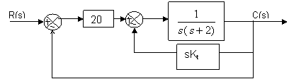
             b.   Determine the derivative feedback constant Kt, which will increase the damping factor of the system to 0.6. What is the steady state error resulting from unit ramp input with this setting of the derivative feedback constant?                                             (6)


  Q.5     a.   Sketch the root locus of the system having  for  .                  (10)


             b.   Examine the stability of , using  Routh’s  criteria.                         (6)


  Q.6     a.   What are Bode plots?  Explain the nature of Bode plot for :                              (10)

                   (i)   pole at origin

                   (ii)  simple pole

                   (iii) simple zero                                                                                                                                                                                                                                                                                                                                                                                                                                                                                                                                                                                                                                                                                                       


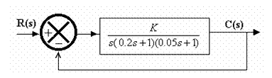
             b.   For the system shown below determine the value of K which give a Phase Margin of 40°.               (6)                                                                                                                                               

Text Box:


  Q.7     a.   State and explain Nyquist stability criterion. How do you study relative stability from Nyquist plot.                                                             (8)                                                                                                                                                                                                                                                     


             b.   Explain the basic modes of feedback control.                                                      (8)                                                                                                                                                                                                                                                                                                                                                                                                    


  Q.8     a.   What is lead compensator? Sketch the Bode plot of lead compensator.               (6)


             b.   Write short notes on                                                                                         (10)

                   (i) Nichol’s chart

                   (ii) Use of Op-Amp for implementation of compensator.                                                                                                                                        10                                                                         


  Q.9     a. For the unity feedback system, the open loop transfer function is   State the type of the system. Also find the position, velocity and acceleration error constant.         (8)                                                                                             


             b.   Discuss the use of digital computer as compensator device.                                (8)