DipIETE – ET (OLD SCHEME)
Code: DE07 Subject: NETWORK AND TRANSMISSION LINES
 Time: 3
Hours
Max. Marks: 100
Time: 3
Hours
Max. Marks: 100
NOTE: There are 9 Questions in all.
· Question 1 is compulsory and carries 20 marks. Answer to Q. 1. must be written in the space provided for it in the answer book supplied and nowhere else.
· Out of the remaining EIGHT Questions answer any FIVE Questions. Each question carries 16 marks.
· Any required data not explicitly given, may be suitably assumed and stated.
Q.1 Choose
the correct or the best alternative in the following: (2 ![]() 10)
10)
a. The VSWR of a wave is 2, its reflection co-efficient will be
(A) 0 (B) 1/2
(C) 1/3 (D) 1
b. The characteristic impedance Zo of a lossless transmission line is
(A) ![]() (B)
(B)
![]()
(C) ![]() (D)
(D)
![]()
c. The
300![]() load is being fed by a 72
load is being fed by a 72![]() transmission line. A quarter-wave
matching section is to be used so as to provide matched condition for a 100 MHz
signal. The length of the section should be
transmission line. A quarter-wave
matching section is to be used so as to provide matched condition for a 100 MHz
signal. The length of the section should be
(A) 0.25m (B) 0.50m
(C) 0.75m (D) 1m
d. Laplace transform of ![]() is
is
(A) ![]() (B)
(B)
![]()
(C) ![]() (D)
(D)
![]()
e. If a capacitor is charged by a square wave current source, the voltage across the capacitor is
(A) a square wave (B) triangular wave
(C) step function (D) zero
f. A constant K-high pass filter is required for a cut-off frequency of 2.5 kHz. The resistance of the circuit is 600 W. The required value of the components are
(A) 19mH, 0.05mF (B) 28mH, 10mF
(C) 11.5mH, 0.5mF (D) 31mH, 50mF
g. The currents flowing in L and C at parallel resonance are
(A) zero (B) equal
(C) infinite (D) different
h. For a prototype Low pass filter, the series and shunt elements are respectively
(A) Capacitive and inductive
(B) Inductive and capacitive
(C) Series combination of capacitance and inductance
(D) Resistive and inductive
i. For a given two part reciprocal network with the transmission parameter
A = 4, B = 7 and C = 8, D is equal to
(A) 16 (B) 14
(C) 3.5 (D) 4.5
j. An ideal voltage source
(A) has terminal voltage in proportion to current
(B) has terminal voltage in proportion to load
(C) has zero internal resistance
(D) has open circuit voltage nearly equal to the voltage on full load
Answer any FIVE Questions out of EIGHT Questions.
Each question carries 16 marks.
Q.2 a. Distinguish between: (8)
(i) Active & Passive elements.
(ii)Linear & Non-linear elements.
b. A DC voltage of 100 V is applied to a circuit having R=10 ohms and L=10 H connected in series. Find
(i) Current at 0.1 sec after switching on
(ii) The time taken by current to reach half of its final value. (8)
Q.3 a. Define an ideal voltage source and an ideal current source. (4)
b. Explain why and how Double tuned circuits are used in Radio receivers? (6)
c. A lossless line of characteristic impedance 300 W is terminated in a pure resistance of 200 W. Find the value of standing wave ratio. (6)
Q.4 a. Use
initial value theorem and final value theorem to find f(0) and f(¥) if ![]() . (4)
. (4)
b. Find
inverse Laplace transform of ![]() . (4)
. (4)
c. A
voltage ![]() is
applied to a series circuit of 10 W
resistance and 1 W inductance. Find i(t). (8)
is
applied to a series circuit of 10 W
resistance and 1 W inductance. Find i(t). (8)
Q.5 a. Derive Characteristic
impedance of symmetrical P(pie) network with series arm
impedance as ![]() and
shunt arm impedance as
and
shunt arm impedance as ![]() (4)
(4)
b. A
symmetrical ![]() section
has an impedance of j100 in the series arm and an impedance of j400
section
has an impedance of j100 in the series arm and an impedance of j400 ![]() in each shunt
arm. Find the characteristic impedance and propagation constant of the
network. (6)
in each shunt
arm. Find the characteristic impedance and propagation constant of the
network. (6)
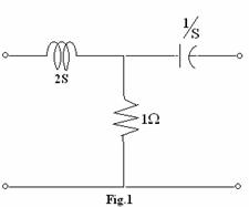
c. Find ABCD parameters for the network shown in Fig.1 (6)
|
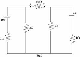
Q.6 a. Determine Thevenin’s equivalent circuit with respect to terminals AB and hence find the current through the 10 W resistance in the Fig.2 (2+6)
|
b. State maximum power transfer theorem. For the circuit shown in Fig.3
|
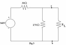
(i) Find the value of RL that results in maximum power being transferred to RL.
(ii) Find the maximum power.
(iii) When RL is adjusted for maximum power transfer, what percentage of power delivered by 360 V source reaches RL. (8)
Q.7 a. A 220 V, 100 Hz AC source supplies a series LCR circuit with a capacitor and a coil. If the coil has 50 mW resistance and 5 mH inductance at a resonance frequency of 100 Hz then calculate:
(i) The value of capacitor.
(ii) The Q factor of the circuit.
(iii) Half power frequencies of the circuit. (8)
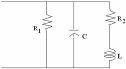
b. Find the input impedance of the network given in Fig. 7(b). Plot the poles and zeros of the input impedance function on the S-plane. (8)
|
||||
|
||||
Q.8 a. Explain how a quarter wave transformer is used for impedance matching in RF line. (6)
b. What is the necessity of loading of lines and explain about different types of loading of lines? (6)
c. If
lossless line has ![]() , what length of the line will be
required to obtain an inductive reactance of
, what length of the line will be
required to obtain an inductive reactance of ![]() , when the far end is short circuited.
Assume the frequency to be 70 MHz. (4)
, when the far end is short circuited.
Assume the frequency to be 70 MHz. (4)
Q.9 a. Design a symmetric ![]() attenuator to
give an attenuation of 60 dB with a line resistance of
attenuator to
give an attenuation of 60 dB with a line resistance of ![]() and derive the relations
used. (8)
and derive the relations
used. (8)
b Draw frequency response of high pass filter. Design a constant K-high pass filter T and P- section having fc = 5 kHz and nominal characteristic impedance, R0=600 W. (2+6)