DipIETE – ET (OLD SCHEME)

 Code: DE03 Subject:
ENGINEERING DRAWING
Code: DE03 Subject:
ENGINEERING DRAWING
Time: 3 Hours Max. Marks: 100
NOTE:
1. (a) There are SEVEN questions in all and these are arranged in three Sections
A, B and C.
(b) Sections A and B are compulsory and carry 20 marks and 32 marks
respectively.
(c) Out of remaining 5 questions (of 16 marks each) in Section C students are
required to answer any 3 questions.
2. Detach this sheet from the question paper and write answers on this sheet
only on Pages 1 & 2. Attach it to the main drawing sheet. Remaining
questions are to be answered on the main drawing sheet.
3. All dimensions given are in mm. Use suitable values of any missing and
mismatching dimensions.
4. Use BIS Code: SP: 46-1988 for all drawings and do not rub off construction
lines.
|
SECTION A (Compulsory)
Note :1. Attach this sheet to the main drawing sheet.
2. Write Answers to Question No. 1 in this sheet only.
Q.1 Write
the correct or the best alternative in the following : (10![]() 2=20)
2=20)
a. The Horizontal Trace (HT) of a line can lie
(A) infront of V.P and in H.P
(B) above H.P and in V.P
(C) below H.P and in V.P
(D) in V.P
b. Rollers in a roller bearing are held in equally spaced position using
(A) inner race (B)
outer race
(C) cage (D) bracket
|
c.
![]() A pentagonal pyramid is cut
by a section plane parallel to its base, the sectioned surface will be
A pentagonal pyramid is cut
by a section plane parallel to its base, the sectioned surface will be
![]()
(A)
trapezium (B)
triangle
(C) rectangle (D) pentagon
d. The development of a triangular prism of base side 30 mm and height of the solid 90 mm will be
(A)
triangle (B) square
(C) rectangle (D) none
e. The projection of cut portion of the solid on HP is called sectional
(A) top view (B) front view
(C) left profile view (D) right profile view
f. If an object lies in IInd quadrant, its position with respect to reference planes will be
(A)
infront of
V.P, above H.P.
(B) behind V.P, above H.P.
(C) behind V.P, below H.P.
(D) infront of V.P below H.P
g. Following R.F is an example for enlarged scale
(A)
12:6000 (B)
6000:12
(C) 300:3000 (D) 300:300
h. The feather keys are parallel keys.
(A) True (B)
False
i. The invisible sides of a solid are shown by thin continuous lines.
|
(A) True (B) False
j. In third angle projection the left profile view lies to left side of projection
(A) True (B) False
SECTION B (Compulsory)
Q.2 The object shown in Fig.1, draw the following views of this object
(i) Front view in the direction of arrow
(ii) Side view from left
(iii) Top view (12+12+8 = 32)
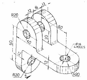
Fig. 1
SECTION C
Answer any THREE Questions. Each question carries 16 marks.
Q.3 A square pyramid of base side 40 mm and height 55 mm is resting with one of its base corners on HP. The slant edge passing through the corner on which it rests is perpendicular to HP and parallel to VP. Draw the
(i) top view (ii) front view (16)
Q.4 A
thin circular disc of 50 mm diameter is placed on HP with its surface making 30![]() with it. The top view of the
diameter passing through the point on which it rests appears to be inclined at
60
with it. The top view of the
diameter passing through the point on which it rests appears to be inclined at
60![]() with X-Y line. Draw the projections of
the disc. (16)
with X-Y line. Draw the projections of
the disc. (16)
Q.5 Draw the involute of a square of 25 mm length of the side. (16)
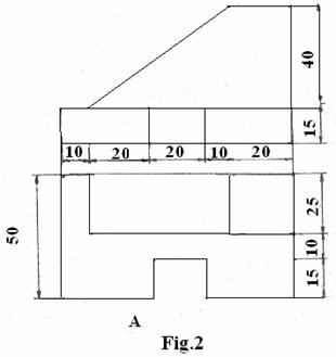
Q.6 Draw the isometric projection of the object ‘A’ shown in Fig.2 (16)
|
Q.7 Draw the (i) top view and (ii) sectional front view of a single riveted butt joint with two cover plates. Take proportionate dimensions. Take thickness of plate as 16 mm. (16)