AMIETE – ET (NEW SCHEME) – Code: AE61
Subject: CONTROL ENGINEERING
Time: 3 Hours Max. Marks: 100
NOTE: There are 9 Questions in all.
· Question 1 is compulsory and carries 20 marks. Answer to Q. 1. must be written in the space provided for it in the answer book supplied and nowhere else.
· Out of the remaining EIGHT Questions answer any FIVE Questions. Each question carries 16 marks.
· Any required data not explicitly given, may be suitably assumed and stated.
Q.1 Choose
the correct or the best alternative in the following: (2![]() 10)
10)
a. Transfer function of the given signal flow graph is
|
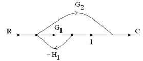
(A) ![]() (B)
(B)
![]()
(C) ![]() (D)
(D) ![]()
b. Velocity error constant is zero in the system of
(A)Type 3 (B) Type 0
(C)Type 1 (D) Type 2
c. As damping factor increases the maximum overshoot
(A) Remains constant (B) Increases
(C)Decreases (D) No relation between them
d. In Force current analogy, the Mass M is analogous to
(A) Current i (B) Capacitance C
(C) Reciprocal
of resistance ![]() (D) Inductance L
(D) Inductance L
e. When the roots are repeated on the imaginary axis then the system is said to be
(A) Unstable (B) Absolutely stable
(C) Conditionally stable (D) Marginarily stable
f. CRL is the locus of variation of roots as K varies from
(A)![]() to +
to +![]() (B)
(B)
![]() to 0
to 0
(C) ![]() to
to ![]() (D)
(D)![]() to 0
to 0
g. Which of the compensator only speeds up the transient response
(A) Lag compensator (B) Lead compensator
(C) Lag – Lead compensator (D) None of the above
h. State variable approach for the analysis and design of
(A) Linear and non-linear systems
(B) Time-invariant and time varying systems
(C) Multi input and multi output systems
(D) All the above.
i. The open
loop transfer function of a certain system is ![]() has the factors
has the factors
(A) Constant gain and pole at the origin
(B) Constant gain, zero at the origin, pole with corner frequency 2
(C) Constant gain, zero with corner frequency 2, pole at the origin and a pole with corner frequency 0.5
(D) Zero with corner frequency 2, pole at the origin and a pole with corner frequency 0.5
j. Frequency at which gain crosses unity is known as
(A) Gain cross over (B) Frequency cross over
(C) Phase cross over (D) Gain margin
Answer any FIVE Questions out of EIGHT Questions.
Each question carries 16 marks.
Q.2 a. Define transfer function. Obtain the transfer function of armature controlled dc motor. (10)
b. Write the differential equations for the mechanical system shown in Fig 2(b) (6)
Q.3 a. The block diagram of
a certain system is shown in the Fig 3(a). Obtain the transfer function ![]() using block
diagram reduction rules. (9)
using block
diagram reduction rules. (9)
b. Obtain the transfer function for the signal flow graph shown in Fig 3(b). (7)
Q.4 a. The
block diagram of a position control system is shown in Fig 4(a). Determine the
sensitivity of closed Loop transfer function T with respect to G and H, for![]() = 1 rad/sec. (8)
= 1 rad/sec. (8)
b. What are the controller components? Explain. (8)
Q.5 a. A unity feedback
system has open loop transfer function ![]()
(i) Calculate the value of gain K so that the closed loop system has a steady state error of 0.1 for unit ramp input.
(ii) Find the corresponding damping factor and overshoot for unit step input. (8)
b. The characteristic equation of a certain control system is given by
![]()
Determine the range of K for the system to be stable. Also find the frequency of sustained oscillations. (8)
Q.6 A unity feedback control system has an open loop transfer function.

Sketch the root locus for 0<K<![]() (16)
(16)
Q.7 a. Explain All-Pass system. (6)
b. Plot the Nyquist plot for a negative feedback control system having an open loop transfer function given by
![]()
Find the range of K for which the system is stable. (10)
Q.8 a. Explain the PI controller. (6)
b. Consider the system shown in Fig 5. Design a lead compensator for this system to meet the following specifications. (10)
Damping ratio ![]() =0.7
=0.7
Setting
time ![]() = 1.4 sec
= 1.4 sec
Velocity
error constant ![]() = 1
= 1 ![]()
Q.9 a. The
transfer function of a certain system is given by
Write down the canonical state variable form. Also draw the state
variable block diagram. (10)
b. Explain the stability analysis by direct method of Liapunov in case of linear system. (6)