AMIETE – ET (NEW SCHEME) – Code: AE59
Subject: CIRCUIT THEORY & DESIGN
 Time: 3
Hours
Max. Marks: 100
Time: 3
Hours
Max. Marks: 100
NOTE: There are 9 Questions in all.
· Question 1 is compulsory and carries 20 marks. Answer to Q. 1. must be written in the space provided for it in the answer book supplied and nowhere else.
· Out of the remaining EIGHT Questions answer any FIVE Questions. Each question carries 16 marks.
· Any required data not explicitly given, may be suitably assumed and stated.
Q.1 Choose
the correct or the best alternative in the following: (2![]() 10)
10)
a. The internal resistance of an ideal voltage source is
(A) infinity (B) zero
(C) 1M![]() (D)
10M
(D)
10M![]()
b. In a network graph the number of branches present in a tree is
(A) n-1 (B) n
(C) n+1 (D) 0
Where ‘n’ is the number of nodes present.
c. Minimum number of equations necessary to analyse a given electrical network by Kirchoff’s voltage law is
(A) n-1 (B) n
(C) b (D) b-(n-1)
Where ‘n’ is the number of nodes and ‘b’ is the number of branches present in the network.
d. What is the equivalent capacitance Ceq for the network shown in Fig 1(d).
|
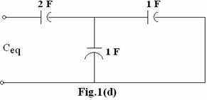
(A) 2F (B) 1.5F
(C) 1F (D) 5F
e. The solution of homogeneous differential equation has
(A) complementary function only (B) particular integral only
(C) Both (D) None
f. Laplace transformation of the function f(t)=1- eat is
(A) ![]() (B)
(B)
![]()
(C) ![]() (D)
(D)
![]()
g.
Final value of the function ![]() is
is
(A) 0 (B) 5
(C) 10 (D) 2
h. If the poles of a system are conjugates, the system is
(A) stable (B) Unstable
(C) Oscillatory (D) Conditionally stable.
i. Single tunner circuits have
(A) Real poles (B) Complex conjugate poles
(C) A pair of conjugate poles (D) A pair of conjugate zeros.
j. The property of LC immittance is that the numerator and denominator always differ in degree by _________
(A) Zero (B) Two
(C) Infinity (D) unity
Answer any FIVE Questions out of EIGHT Questions.
Each question carries 16 marks.
Q.2 a. What are a Controlled Sources? Explain the four types of Controlled Sources with three terminal models. (6)
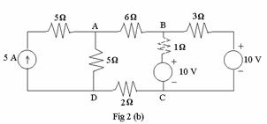
b. For
the network shown in Fig 2(b), determine the voltages at nodes A and B
using (i) Loop analysis (ii) Nodal analysis. Consider node D as datum
node. (10)
Q.3 a. A
series RC branch with RC= 20 ![]() and C=1
and C=1 ![]() F is shunted by an inductor
of resistance RL=20
F is shunted by an inductor
of resistance RL=20 ![]() and inductance 1 H. This is supplied
by a DC source of 100 V through a series resistance of 10
and inductance 1 H. This is supplied
by a DC source of 100 V through a series resistance of 10 ![]() . There is a switch across
10
. There is a switch across
10 ![]() which
is closed at t=0. Solve for the current in L and C and their
derivatives at t=0+. (10)
which
is closed at t=0. Solve for the current in L and C and their
derivatives at t=0+. (10)
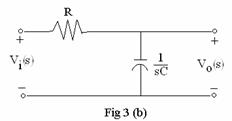
b. Find the amplitude and
phase response of the network shown in Fig 3(b). (6)
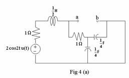
Q.4 a. Use Thevenin’s theorem to determine the Thevenin’s equivalent impedance at terminals ab for the network shown in Fig 4(a). (8)
|
b. If
the capacitors are unenergised and induction current is 0 at
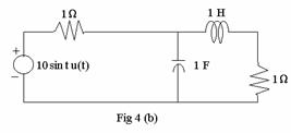
![]() in the network shown in Fig
4(b), show that the transform of the generator current is
in the network shown in Fig
4(b), show that the transform of the generator current is  (8)
(8)
Q.5 a. In the network
shown in Fig 5(a), the switch k is moved from position a to b
at t=0, a steady state having been established at position a.
Solve for current i(t) using Laplace transform method. (8)

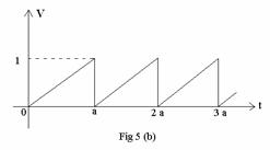
b. The waveform in Fig 5(b) is a sweep voltage used to deflect the beam in cathode ray oscilloscope. Find the Laplace transform of it. (8)
|
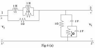
Q.6 a. For
the network shown in Fig 6 (a), show that with port 2 open, the input impedance
at port 1 is 1![]() .
Find the voltage ratio transfer function G12 for given the two port
network. (10)
.
Find the voltage ratio transfer function G12 for given the two port
network. (10)
|
b. Synthesize
the positive real function ![]() by first removing
by first removing
min [Re (Y(jw))]. (6)
Q.7 a. Obtain expressions for Y parameter in terms of Z and h parameters (8)
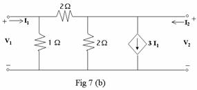
b. Find Y and Z parameters of the given network shown in Fig.7(b). (8)
Q.8 a. Determine the Foster
forms of LC driving point immittance function given by  (8)
(8)
b. The
driving point impedance function of RC network is given by realise the network in Cauer
form. (8)
realise the network in Cauer
form. (8)
Q.9 a. Synthesize
the function given below with a 1 ![]() termination.
termination.
![]() (10)
(10)
b. Write a note on magnitude and frequency normalization used in filter design. (6)