AMIETE – ET (OLD SCHEME)
Code: AE08 Subject: CIRCUIT THEORY & DESIGN
 Time:
3
Hours
Max. Marks: 100
Time:
3
Hours
Max. Marks: 100
NOTE: There are 9 Questions in all.
· Question 1 is compulsory and carries 20 marks. Answer to Q. 1. must be written in the space provided for it in the answer book supplied and nowhere else.
· Out of the remaining EIGHT Questions answer any FIVE Questions. Each question carries 16 marks.
· Any required data not explicitly given, may be suitably assumed and stated.
Q.1 Choose
the correct or the best alternative in the following: (2 ![]() 10)
10)
a.
In the circuit
shown, I is given by
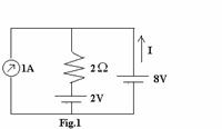
(A) –2A.
(B) 2A.
(C) 3A.
(D) 4A.
b. A series RLC circuit has R=10,000 ohms, L=10mH, C=1μF. The resonant frequency ωo(rad/sec) is given by
(A)
![]() . (B)
. (B)
![]() .
.
(C) ![]() . (D)
. (D)
![]() .
.
c. 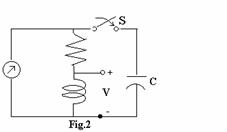 In the circuit shown, steady state is reached
with
S-open. S is closed at t=0 At t= ![]() , the voltage across ‘L’ is given by
, the voltage across ‘L’ is given by
(A) 0.
(B) 6.
(C) –6.
(D) 2.
d. An
instantaneous voltage of ![]() is applied across an element and the
instantaneous power is observed to be
is applied across an element and the
instantaneous power is observed to be ![]() Then the element is a
Then the element is a
(A) Resistor. (B) Inductor.
(C) Capacitor. (D) None of the above.
e. A system function
![]() . The
system is at rest for t<0. i(t)=unit step, is given at t = 0 then v(t) for
t > 0 is given by
. The
system is at rest for t<0. i(t)=unit step, is given at t = 0 then v(t) for
t > 0 is given by
(A)
![]() . (B)
. (B)
![]() .
.
(C) ![]() . (D)
. (D)
![]() .
.
f. The current
i(t), through a 10Ω resistor in series with an inductance, is given by ![]() Amperes. The RMS
value of the current in the circuit is
Amperes. The RMS
value of the current in the circuit is
(A) ![]() . (B)
. (B)
![]() .
.
(C) 5A. (D) 11A.
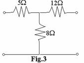
g. Determine the z-parameters of the network
shown in Fig.3
(A) 5, 8, 12, 0
(B) 13, 8, 8, 20
(C) 8, 20, 13, 12
(D) 5, 8, 8, 12
h. The condition AD–BC=1 for a two port network implies that the network is a
(A) reciprocal network. (B) lumped element network.
(C) lossless network. (D) unilateral element network.
 i. The value of the
resistance ‘R’ in Fig.4 shown is adjusted such that the power dissipated in the
2Ω resistor
i. The value of the
resistance ‘R’ in Fig.4 shown is adjusted such that the power dissipated in the
2Ω resistor
is maximum. Under this condition
(A) The value of R is zero ohm.
(B) The value of R is 4 ohms.
(C) The power dissipated in the
2 ohms resistor is18W.
(D) The value of R is 2 ohms.
j. The value of R in the Fig.5 is
adjusted
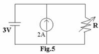
so that Power developed by the voltage
source is zero Watt. The value of R is
(A)
![]() .
.
(B) ![]() .
.
(C) ![]() .
.
(D) ![]() .
.
Answer any FIVE Questions out of EIGHT Questions.
Each question carries 16 marks.
|
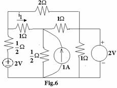
Q.2 a. For the network shown in Fig.6, determine the numerical value of the branch current i1. All the sources in the network are time invariant.
(8)
|
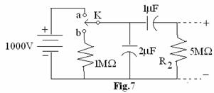
b. With switch K in a position a, the network shown in Fig.7 attains equilibrium. At time t=0, the switch is moved to position b. Find the voltage across R2 as a function of time.
(8)
Q.3 a. In
the network shown in the Fig.8, a steady state is reached with the switch K
open. At t=0, the switch is closed.
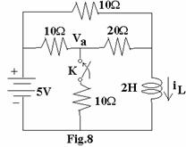
For the element values given,
determine the value of Va(0–) and
Va(0+). (8)
|
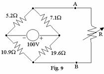
b. Use the Thevenin equivalent of the network shown in Fig.9 to find the value of R which will receive maximum power. Find also this power. (8)
Q.4 a. Given the ABCD parameters of two port network determine its ‘Z’ parameter. (8)
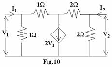
b. Find the y-parameters of the circuit shown in Fig.10. (8)
|
Q.5 a. State the Hurwitz
criteria for stability. Determine whether the given polynomial ![]() is Hurwitz or
not? (8)
is Hurwitz or
not? (8)
b. Explain the following:
(i) phasor (ii) Resonance
(iii) Q (iv) Damping coefficient (8)
 Q.6 a. For the shunt
peaking circuit shown in Fig.11 that the admittance Y(s) is of the form
Q.6 a. For the shunt
peaking circuit shown in Fig.11 that the admittance Y(s) is of the form ![]() express s1,
s2 and s3 in terms of R, L and C. (8)
express s1,
s2 and s3 in terms of R, L and C. (8)
(8) (8)
b. Determine the amplitude and phase for F(J1) from the pole-zero
plot in s-plane for the network function ![]() (8)
(8)
Q.7 a. Check whether the
function
![]() is a positive real function. (8)
is a positive real function. (8)
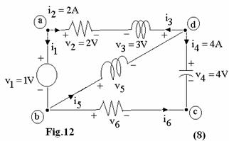
b. Using Kirchhoff’s laws to
the network shown in Fig.12, determine the values of ![]() and
and ![]() . Verify that the network
satisfies Tellegen’s theorem.
. Verify that the network
satisfies Tellegen’s theorem.
Q.8 a. Find the networks
for the following function in I Foster and I Caver form ![]() . (8)
. (8)
b. Synthesize the voltage
ratio  as a constant resistance bridged-T
network terminated in a 1Ω resistor. (8)
as a constant resistance bridged-T
network terminated in a 1Ω resistor. (8)
Q.9 a. The
input impedance for the network shown in Fig.13 is
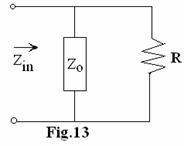
![]() .
.
If Zo is an LC network:
(i) find the expression for Zo.
(ii) synthesize Zo in a Foster series form. (8)
b. Synthesize the 3rd order low pass Butterworth filter terminated in a 1Ω load resistance. (8)