Code: AE26 Subject: POWER ELECTRONICS
Time: 3 Hours Max. Marks: 100
NOTE: There are 9 Questions in all.
· Question 1 is compulsory and carries 20 marks. Answer to Q. 1. must be written in the space provided for it in the answer book supplied and nowhere else.
· Out of the remaining EIGHT Questions answer any FIVE Questions. Each question carries 16 marks.
· Any required data not explicitly given, may be suitably assumed and stated.
Q.1 Choose the correct or best alternative in the following: (2x10)
a. Natural commutation can be used in
(A) DC circuit only (B) AC circuit only
(C) Both AC & DC circuits (D) None of the above
b. A thyristor when conducting, the voltage drop across it is:
(A) 1 V (B) 10 V
(C) 100 V (D) 0.1 V
c. A thyristor is feeding an R-L load, the turn on time can be reduced by:
(A) Decreasing R (B) Decreasing L
(C) Increasing L (D) Decreasing R and increasing L
d. In dc choppers, the waveform for input is __________ and waveform of output is _____________.
(A) discontinuous; continuous (B) continuous; discontinuous
(C) both discontinuous (D) both continuous
e. Power factor at the input terminals of a cycloconverter is generally:
(A) low, leading (B) low, lagging
(C) high, leading (D) high, lagging
f. A single phase voltage controller is employed in controlling the power flow from 260V, 50Hz source into load of R=3Ω, ωL=4Ω. The control range of firing angle will be
(A) 0º – 53.13º (B) 53.13º – 180º
(C) 0º – 180º (D) none of these
g. A dual converter consists of two fully controlled converters connected in anti parallel.
(A) True (B) False
h. A UJT is used to commutate a thyristor.
(A) True (B) False
i. In sinusoidal pulse width modulation, the frequency of control signal, controls the frequency of output.
(A) True (B) False
j. An IGBT has low losses as well as low switching times.
(A) True (B) False
Answer any FIVE Questions out of EIGHT Questions.
Each question carries 16 marks.
Q.2 a. What is IGBT? Describe its construction. Give comparison of power MOSFET with IGBT. (10)
b. The R, L and C in an SCR circuit meant for protecting against ![]() and
and ![]() are
4Ω, 6μH and 6μF respectively. If the supply voltage is 300V,
find the maximum permissible values of
are
4Ω, 6μH and 6μF respectively. If the supply voltage is 300V,
find the maximum permissible values of ![]() and
and ![]() .
(6)
.
(6)
Q.3 a. Discuss extinction angle control for power factor improvement of three phase dual converter. (8)
b. A single phase full converter is supplied from 230V, 50Hz source. The load consists of R=10Ω and a large inductance so as to render the load current constant. For firing angle delay of 30º, determine (i) average output voltage, (ii) average output current, (iii) average and rms value of thyristor current and (iv) power factor. (8)
Q.4 a. What is chopper? How choppers are classified. Draw their circuits and explain their working briefly. (9)
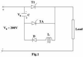
b. In the circuit of Fig.1, a highly inductive load is fed from the 200V supply through a chopper, has an average current of 50A and peak load current is 60A. The chopping frequency is 500Hz, and the turn off time of the main thyristor T1 is 15μsec. The peak current of the thyristor should not exceed 150% of the peak current of load. Find L & C for the chopper circuit shown below. (7)
Q.5 a. Draw circuits and explain any two methods for forced commutation of thyristors. (8)
b. What is GTO Thyristor? Discuss its operation. (8)
Q.6 a. Draw diagram to illustrate the principle of on-off control. Derive the equation for rms output voltage. Give the advantages and disadvantages of on-off control. (10)
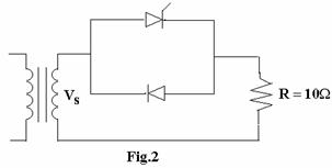
b. A single phase ac voltage controller in Fig.2, has a resistive
load of R=10Ω and the input voltage is Vs=120V, 60Hz. The delay
angle of thyristor T is ![]() . Determine
. Determine
(i) the rms value of output voltage,
(ii) the input power factor and
(iii) the average input current (6)
Q.7 a. Explain the working of 3 phase to three phase cycloconverter. (8)
b. Explain Blocked group operation of cycloconverter. (8)
Q.8 a. What do you understand by voltage control of three phase inverter? Discuss briefly, the methods for voltage control. (8)
b. How the working of full bridge single phase inverter is different from that of half bridge circuit. Explain with the help of diagrams. (8)
Q.9 a. Draw Schematic diagram for firing control of dual converter using microprocessor. (7)
b. A one quadrant chopper is used for rheostatic braking of a separately excited dc motor. When armature resistance Ra=0.1Ω, braking
resistance = 7.5Ω, voltage constant = 1.4V/A-rad/sec,
armature current = 120A and field current is 1.6A, the duty cycle of the chopper is 0.35. Find
(i) average voltage across chopper
(ii) power dissipated in braking resistance and.
(iii) motor speed (9)