 Code: AE11 Subject:
CONTROL ENGINEERING
Code: AE11 Subject:
CONTROL ENGINEERING
Time: 3 Hours Max. Marks: 100
NOTE: There are 9 Questions in all.
· Question 1 is compulsory and
carries 20 marks. Answer to Q. 1. must be written in the space provided for it
in the answer book supplied and nowhere else.
· Out of the remaining EIGHT
Questions answer any FIVE Questions. Each question carries 16 marks.
· Any required data not
explicitly given, may be suitably assumed and stated.
Q.1 Choose
the correct or best alternative in the following: (2x10)
a. A second-order system with
damping ratio of 0.4 acting on a unit-step input will produce a maximum
overshoot of about
(A) 25% (B)
45%
(C) 65% (D) 85%
b. The number of counter clockwise encirclements (N) of the critical point(–1+j0) in the signal-flow graph shown in Fig.1b is
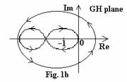
(A)
3 (B)
2
(C) 0 (D)
1
c. A mass M initially at rest acted upon by a force F(t) as shown in Fig.1c is described by
(A)
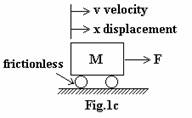
 (B)
(B)

(C) ![]() (D)
(D)
![]()
d. The transfer function of a dead-time element
is
(A) ![]() (B)
(B) ![]()
(C) ![]() (D)
(D) ![]()
e. A synchro transmitter-receiver pair is most widely used in feedback control systems as
(A)
frequency
detector (B) error
detector
(C) modulator (D)
amplifier
f. The transfer function from ![]() to
to ![]() for a tachogenerator of sensitivity Kt has the
form
for a tachogenerator of sensitivity Kt has the
form ![]() =
=
(A) Kt (B) ![]()
(C) ![]() (D) s Kt
(D) s Kt
g. The LVDT is primarily used for the measurement of
(A) displacement (B)
velocity
(C) acceleration (D)
humidity
h. Consider the function ![]() , where
, where ![]() is the
is the ![]() is equal to
is equal to
(A) 5. (B) ![]() .
.
(C) zero. (D) infinity.
i. Routh-Hurwitz criterion applied to the
characteristic equation ![]() shows that the system is
shows that the system is
(A) absolutely stable (B)
unstable
(C) marginally stable (D) conditionally stable
j. A system for which the steady state error is a finite constant for a unit step input is of type
(A) 1 (B)
2
(C) 0 (D)
1 or 2
Answer any FIVE Questions out
of EIGHT Questions.
Each
question carries 16 marks.
Q.2 a. Consider the mechanical system of Fig.2a.
Obtain the transfer function
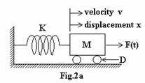
![]() , assuming zero initial conditions. Draw the corresponding
electric network using the force-voltage analogy. (8)
, assuming zero initial conditions. Draw the corresponding
electric network using the force-voltage analogy. (8)
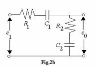
b. Obtain the
transfer-function model as the overall block-diagram for the electric network
of Fig.2b and also its mechanical equivalent.
(8)
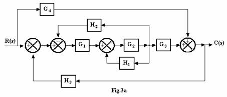
Q.3 a. By block-diagram reduction technique, obtain
the overall transfer function for Fig.3a. (8)
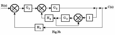
b. Draw
the equivalent signal-flow graph for the block-diagram of Fig.3b, and then
apply Mason's general gain rule to get the overall transfer function. (8)
Q.4 a. The characteristic equation of a control
system is given as ![]() . Determine the range
of ‘k’ for stability using Routh-Hurwitz criterion. (8)
. Determine the range
of ‘k’ for stability using Routh-Hurwitz criterion. (8)
b. The
closed-loop transfer-function of a second order system is given by  , where
 ![]() is the undamped natural frequency and
is the undamped natural frequency and ![]() the damping ratio.
Show that for a unit step input r(t)=u(t), the output c(t) may be represented
as the sum of steady-state and transient response. (8)
the damping ratio.
Show that for a unit step input r(t)=u(t), the output c(t) may be represented
as the sum of steady-state and transient response. (8)
Q.5 a. The
open-loop transfer function of a system is ![]() . Sketch the root-locus on a graph-sheet and indicate the
points for K=0,1,2. Find the damping ratio
. Sketch the root-locus on a graph-sheet and indicate the
points for K=0,1,2. Find the damping ratio![]() for K=2. Is the system stable for K=2? (8)
for K=2. Is the system stable for K=2? (8)
b. For
a feedback control system with open-loop transfer function G(s) and feedback
H(s), derive the expression for steady-state error ess. Obtain ess
in terms of position error constant Kp, velocity error constant Kv
and acceleration error constant Ka, respectively, for input r(t)=u(t), t u(t)
and t2/2. (8)
Q.6 a. Using
Nyquiest Criterion, determine whether the closed-loop system is stable: ![]() . (10)
. (10)
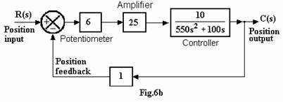
b. The
block-diagram of a remote position control of a ship's rudder is given in
Fig.6b. Write the overall transfer-function and determine the damping ratio![]() and the natural frequency
and the natural frequency ![]() of the system. (6)
of the system. (6)
Q.7 a. A control system ![]() has unity feedback. Draw the Bode plots on a semilog graph
sheet and determine:
has unity feedback. Draw the Bode plots on a semilog graph
sheet and determine:
(i) gain crossover frequency and phase-margin
(ii) phase crossover frequency and gain margin (10)
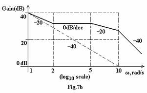
b. Fig.7b shows the Bode asymptote plot. Determine the open-loop
transfer function G(s) of the
system. (6)
Q.8 a. Describe the PID
controller and explain how the various parameters of the controller affect the
performance of a feedback control system. (8)
b. Obtain
the transfer function for the lead compensator network of Fig.8b in terms of
the system time constant
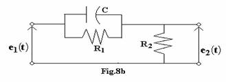
![]() and
and ![]() . Draw the pole-zero plot of the transfer function. (8)
. Draw the pole-zero plot of the transfer function. (8)
Q.9 Write short note on any TWO:-
(i)
Synchronous
transmitter
(ii)
Controller
tuning
(iii)
Digital
computer as compensation devices. (8 + 8)