 Code: AE08 Subject:
CIRCUIT THEORY & DESIGN
Code: AE08 Subject:
CIRCUIT THEORY & DESIGN
Time: 3 Hours Max. Marks: 100
NOTE: There are 9 Questions in all.
· Question 1 is compulsory and
carries 20 marks. Answer to Q. 1. must be written in the space provided for it
in the answer book supplied and nowhere else.
· Out of the remaining EIGHT
Questions answer any FIVE Questions. Each question carries 16 marks.
· Any required data not
explicitly given, may be suitably assumed and stated.
Q.1 Choose
the correct or best alternative in the following: (2x10)
a.
The
value of z22
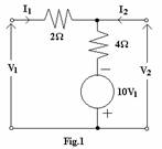
![]() for the circuit of
Fig.1 is:
for the circuit of
Fig.1 is:
(A) ![]() (B)
(B)
![]()
(C) ![]() (D)
(D) ![]()
b.
A possible tree of the topological equivalent
of the network of Fig.2 is
![]()
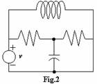
(A)
![]()
(B)
(C) Neither (A)
nor (B)
(D) Both (A)
and (B)
c.
Given ![]() then
then ![]() is
is
(A) 1 (B) 2
(C) 0 (D) 3
d.
The two-port matrix of an n:1
ideal transformer is  . It describes the transformer in terms of its
(A)
z-parameters. (B) y-parameters.
(C) Chain-parameters. (D) h-parameters.
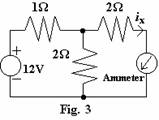
e. The value of ix(A) (in the circuit of Fig.3) is
(A) 1 (B)
2
(C) 3 (D) 4
f. To effect maximum power transfer to the
load, ZL
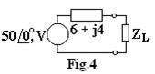
![]() in Fig.4 should be
in Fig.4 should be
(A) 6
(B) 4
(C) ![]()
(D) ![]()
g. The poles of a stable Butter worth polynomial lie on
(A) parabola (B) left semicircle
(C) right semicircle (D)
an ellipse
h. If ![]() and
and ![]() are p.r., then which
of the following are p.r. (Positive Real)?
are p.r., then which
of the following are p.r. (Positive Real)?
(A) ![]() and
and ![]() (B)
(B) ![]()
(C) ![]() (D) All of these
(D) All of these
i. For the pole-zero of Fig.5, the network function is
(A)
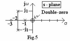
![]()
(B)
![]()
(C) 
(D) 
j. For
a series R-C circuit excited by a d-c voltage of 10V, and with time-constant ![]() the voltage across C
at time
the voltage across C
at time ![]() is given by
is given by
(A) ![]() (B)
(B) ![]()
(C) ![]() (D)
(D) ![]()
Answer any FIVE Questions out
of EIGHT Questions.
Each question carries 16
marks.
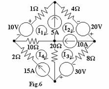
Q.2 a. Determine the loop currents, I1, I2,
I3 and I4 using mesh (loop) analysis for the network
shown in Fig.6. (8)
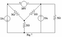
b. Find the power
delivered by the 5A current source (in Fig.7) using nodal analysis. (8)
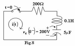
Q.3 a. The capacitor in the
circuit of Fig.8 is initially charged to 200V. Find the transient current after
the switch is closed at t=0. (8)
b. Determine the r.m.s. value of current, voltage drops across R and L, and
power loss when 100 V
(r.m.s.), 50 Hz is applied across the series combination of R=6![]() and
and![]() H. Represent the current and voltages on a phasor diagram. (8)
H. Represent the current and voltages on a phasor diagram. (8)
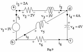
Q.4 a. Using Kirchhoff’s laws to the network shown
in Fig.9, determine the values of ![]() and
and ![]() . Verify that the
network satisfies Tellegen’s theorem. (8)
. Verify that the
network satisfies Tellegen’s theorem. (8)
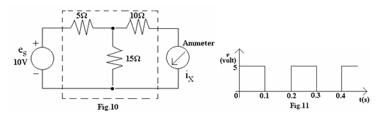
b. State Reciprocity
Theorem for a linear, bilateral, passive network. Verify reciprocity for the
network shown in Fig.10. (8)
Q.5 a. Find
(i) the r.m.s. value of the square-wave shown in Fig.11.
(ii)
the average power for the circuit having ![]() when the driving
current is
when the driving
current is ![]() (8)
(8)
b. The voltage across an impedance is 80+j60 Volt, and the current though it is 3+j4 Amp. Determine the impedance and identify its element values, assuming frequency to be 50Hz. From the phasor diagram, identify the lag or lead of current w.r.t. voltage. (8)
Q.6 a. Consider
the function Plot its poles and zeroes. Sketch the amplitude and phase
for F(s) for
Plot its poles and zeroes. Sketch the amplitude and phase
for F(s) for ![]() (8)
(8)
b. Determine whether the
function ![]() is positive real or
not. (8)
is positive real or
not. (8)
Q.7 a. Given
the Z parameters of a two-port network, determine its Y parameters. (8)
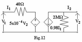
b. Find the y-parameters for
the two-port network of
Fig.12. (8)
Q.8 a. Synthesise a one-port L-C network whose driving-point impedance is
 (8)
(8)
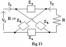
b. Determine the condition for a lattice
terminated in R as shown in Fig.13 to be a constant-resistance network. (8)
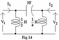
Q.9 a. Find the y-parameters of the circuit of
Fig.14 in terms of s. Identify the poles of yij(s). Verify whether
the residues of poles satisfy the general property of L-C two-port networks. (8)
b. A third-order Butterworth
polynomial approximation is desired for designing a low-pass filter. Determine
H(s) and plot its poles. Assume unity d-c gain constant. (8)