 Code: DE15 Subject:
CONTROL ENGINEERING
Code: DE15 Subject:
CONTROL ENGINEERING
Time: 3 Hours Max. Marks: 100
NOTE: There are 9 Questions in all.
· Question 1 is compulsory and carries 20 marks. Answer to Q. 1. must be written in the space provided for it in the answer book supplied and nowhere else.
· Out of the remaining EIGHT Questions answer any FIVE Questions. Each question carries 16 marks.
· Any required data not explicitly given, may be suitably assumed and stated.
Q.1 Choose the correct or best alternative in the following: (2x10)
a. The transfer function of any system is defined as the ratio of
(A) output to input considering initial conditions as zero.
(B) Laplace transform of input to laplace transform of output considering initial conditions to zero.
(C) Laplace transform of output to laplace transform of input considering initial conditions as zero
(D) Laplace transform of output to laplace transform of input
b. A closed loop system is
(A) less accurate (B) easy to build
(C) may become unstable at times (D) stability can be ensured
c. In force-voltage analogy, velocity is analogous to
(A) current (B) charge
(C) inductance (D) capacitance
|
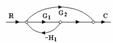
d. Transfer function for the given
signal flow graph is
(A) ![]() (B)
(B) ![]()
(C) ![]() (D)
(D)
![]()
e. For the system ![]() , the damping
factor
, the damping
factor ![]() and
damped frequency of oscillations
and
damped frequency of oscillations ![]() respectively will be
respectively will be
(A) 0.6, 4 (B) 0.4, 6
(C) 0.5, 3 (D) 0.3, 5
f. For input ![]() the steady output
for the transfer function
the steady output
for the transfer function ![]() is
is
(A) 0 (B) 0.5
(C) 1.5 (D) 2
g. The characteristic equation of a system is given as
![]()
the system is stable if
(A) K>12 (B) K=12
(C) K>3 (D) K<8
h. The initial slope of the Bode plot for a type 2 system with Bode gain(K) intersects 0dB axis at
(A)
![]() (B)
(B)
![]()
(C) ![]() (D)
(D) ![]()
i. In order to increase the damping of a badly underdamped system which of the following compensator may be used?
(A) Phase lead (B) Phase lag
(C) Both (A) and (B) (D) None of the above
j. The break away points of the root locus occur at
(A) Imaginary axis
(B) Real axis
(C) Multiple roots of characteristic equation
(D) None of the above
Answer any FIVE Questions out of EIGHT Questions.
Each question carries 16 marks.
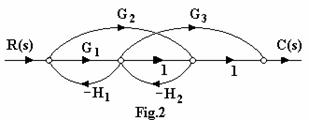
Q.2 a. Obtain
the overall transfer function for the signal Flow Graph shown in Fig.2. (8)
|
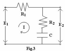
b. Obtain the transfer function ![]() for the electrical system
shown in Fig.3.
for the electrical system
shown in Fig.3.
(8)
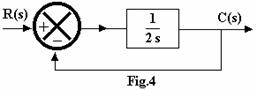
Q.3 a. Define
Time constant and explain its effect on system response. Find the unit step
response and value of time constant for first order system shown in Fig.4.
(8)
b. What is a state variable? Elaborate upon the basis of selecting suitable state variables for a system. (8)
Q.4 a. In designing of control system, the following aspect must be taken into account (a) stability (b) Input amplitude constraints (c) sensitivity and robustness (d) Disturbance rejection. Explain the significance of each. (8)
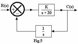
b. Determine the values of K for the control system shown in Fig.5, if the system has a steady state error (ess) of 0.02 to a unit ramp input. (8)
|
Q.5 a. Define stability, absolute stability, relative stability and conditional stability. (8)
b. A unity feedback
control system has an open loop transfer function ![]() . Determine the range of K
for the system to be stable. (8)
. Determine the range of K
for the system to be stable. (8)
|
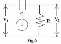
Q.6 a. Find the transfer function of a lead network shown in Fig.6.
Show that the polar plot of above system is a semi-circle. Given that R=1![]() and C=1F. (8)
and C=1F. (8)
b. Draw the Nyquist plot
for the given open loop transfer function of a unity feed back system and
comment on the stability of system. ![]() . (8)
. (8)
Q.7 Construct
the bode plot for a unity feedback control system having ![]() Obtain the value of Gain Margin
(GM) and Phase Margin (PM). Comment on the stability of system. (16)
Obtain the value of Gain Margin
(GM) and Phase Margin (PM). Comment on the stability of system. (16)
Q.8 a. Derive
an expression for maximum phase lead ![]() and corresponding frequency
and corresponding frequency ![]() at which
at which ![]() occurs for a lead compensator
whose transfer function is given as
occurs for a lead compensator
whose transfer function is given as ![]() where
where ![]() (8)
(8)
b. Discuss in detail Operational Amplifier usage. (8)
Q.9 Write short notes on (16)
(i) Synchros
(ii) PID control action
|