 Code:
AE11 Subject:
CONTROL ENGINEERING
Code:
AE11 Subject:
CONTROL ENGINEERING
Time: 3 Hours Max. Marks: 100
NOTE: There are 9 Questions in all.
· Question 1 is compulsory and carries 20 marks. Answer to Q. 1. must be written in the space provided for it in the answer book supplied and nowhere else.
· Out of the remaining EIGHT Questions answer any FIVE Questions. Each question carries 16 marks.
· Any required data not explicitly given, may be suitably assumed and stated.
Q.1 Choose the correct or best alternative in the following: (2x10)
a. If force-current and velocity-voltage are analogous pairs, then mass is paired with
(A) Capacitance (B) Inductance
(C) Resistance (D) Conductance
b.
The system with input-output

behaviour shown in Fig.1 will have
(A) linear elements
(B) active elements
(C) dead-time elements
(D) ideal elements
c. The controller of gain ![]() and rate-time
and rate-time ![]() as in Fig.2 refers to
as in Fig.2 refers to

(A) PID
(B) PD
(C) PI
(D) Integral controller
d. If for all
possible initial states ![]() eventually decays to zero as
eventually decays to zero as ![]() , then the system
is
, then the system
is
(A) stable (B) unstable
(C) marginally stable (D) asymptotically stable
e. The radii of
constant-M circles reduce monotonically and the centres located on the negative
real axis shift towards ![]() point when
point when
(A) M = 1 (B) M > 1
(C) M < 1 (D) M = 0
f. Control applications using synchros require good sensitivity which has the units
(A) V (B) rpm
(C) ![]() (D)
(D)
![]()
g. Consider a function
![]() where
L
where
L![]() then
then
equal to
![]()
(A) zero (B) one
(C) infinite (D) none of the above
h. Large power applications like earth station antenna drives for tracking satellites generally use
(A) ac servo motors (B) dc servo motors
(C) small motors (D) single-phase motors
i. For a standard
second-order system described by ![]() , the term
, the term ![]() indicates
indicates
(A) time-constant (B) damping factor
(C) natural frequency (D) none of the above
j. The root-locus drawn in Fig.3 refers to an open-loop transfer function G(s) =
(A)

![]()
(B) ![]()
(C) ![]()
(D) ![]()
Answer any FIVE Questions out of EIGHT Questions.
Each question carries 16 marks.
Q.2 a. For
the mechanical system of Fig.4, draw the free body diagram and write the
associated equations of motion. Draw the electrical equivalent circuit using
F(t)
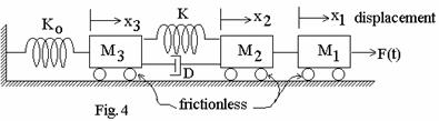
![]() voltage
and
voltage
and ![]() current
analogy. (8)
current
analogy. (8)
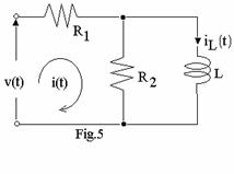
b. Write the transfer function for each element of the network of Fig.5 and derive the transfer function of the network. (8)
Q.3 a. Reduce the block-diagram
of Fig.6 to find
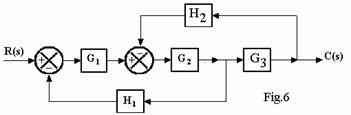
![]() . (8)
. (8)
b. Use Mason’s gain rule to obtain the overall transfer function of the signal-flow graph of the block-diagram of Fig.7. (8)
|

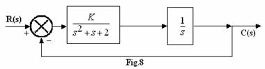
Q.4 a. Apply Routh-Hurwitz criterion to find the greatest value of K that can keep the system of Fig.8 stable. Also state Routh-Hurwitz criterion for stability of a feedback control system. (10)
|
b. Discuss the various time domain performance specification of a typical second-order system with unit input excitation. (6)
Q.5 a. Sketch the
root-locus on a graph sheet for a control system with ![]() . Mark the points of
intersection with the real-axis. (8)
. Mark the points of
intersection with the real-axis. (8)
b. The block diagram of a servo system
shown in Fig.9 has K = 10. Determine the values of a and b, if the
time-constant is 0.1s and damping ration

![]() . (8)
. (8)
Q.6 a. For the open-loop transfer-function ![]() ,
draw the Nyquist plot. Verify whether the system is stable. (10)
,
draw the Nyquist plot. Verify whether the system is stable. (10)
b. For the unity-feedback system ![]() find the type
of the system, the error constants
find the type
of the system, the error constants ![]() and the corresponding steady-state
errors. (6)
and the corresponding steady-state
errors. (6)
Q.7 a. Draw
Bode plots on a semilog graph sheet for ![]() , H(s) = 1. Find the value of K if
the phase-margin is to be
, H(s) = 1. Find the value of K if
the phase-margin is to be ![]() . What is the corresponding
gain-margin? (10)
. What is the corresponding
gain-margin? (10)
b. An electronic pace-maker controlling the rate of heartbeat is shown in Fig.10
|
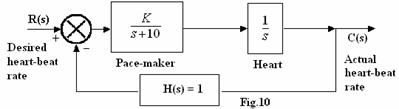
Determine the value of K to limit the steady-state error to 0.02 for a ramp input. (6)
Q.8 a. Discuss tunning of PID controller. (6)
b. Represent the following data on a graph sheet to show a frequency-response plot in Nichols coordinate system. Determine the phase-margin and the gain-margin. Also define the term phase-margin and gain-margin. (10)
|
Frequency,w, rad/s |
0.2 |
0.5 |
0.78 |
1.25 |
2.2 |
3.0 |
|
Gain, dB |
15 |
5 |
0 |
–7 |
–15 |
–21 |
|
Phase, deg. |
–110 |
–120 |
–140 |
–160 |
–180 |
–190 |
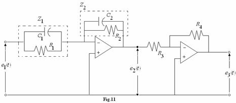
Q.9 a. Consider the opamp circuit used as a compensator. (Fig.11) Show that
(i) ![]() makes it a lead
compensator.
makes it a lead
compensator.
(ii)
![]() makes
it a lag compensator. (10)
makes
it a lag compensator. (10)
|
b. Explain phase-lead compensation. (6)