 Code:
AE08 Subject:
CIRCUIT THEORY & DESIGN
Code:
AE08 Subject:
CIRCUIT THEORY & DESIGN
Time: 3 Hours Max. Marks: 100
NOTE: There are 9 Questions in all.
· Question 1 is compulsory and carries 20 marks. Answer to Q. 1. must be written in the space provided for it in the answer book supplied and nowhere else.
· Out of the remaining EIGHT Questions answer any FIVE Questions. Each question carries 16 marks.
· Any required data not explicitly given, may be suitably assumed and stated.
Q.1 Choose the correct or best alternative in the following: (2x10)
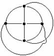
a.
Example of a
planar graph is
|

(A) (B)
|
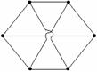
(C) (D) None of these
|
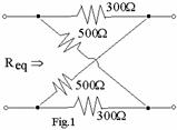
b. The value of ![]() for the circuit of Fig.1 is
for the circuit of Fig.1 is
(A) 200 (B) 800
(C) 600 (D) 400
c. A 2 port network using Z parameter representation is said to be reciprocal if
(A) Z11 = Z22 (B) Z12 = Z21
(C) Z12 = –Z21 (D) Z11Z22 – Z12Z21 = 1
d. The phasor diagram shown in Fig.3 is
for a two-element series circuit having
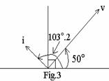
(A)
R and
C, with tan ![]()
(B)
R and
C, with tan ![]()
(C) R and L, with tan ![]()
(D) R and L, with tan ![]()
e. The condition for maximum power transfer to the load for Fig.4 is
(A)
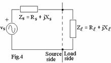
![]()
(B)
![]()
(C) ![]()
(D) ![]()
f. The instantaneous power delivered
to the
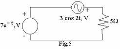
![]() resistor at t=0 is
(Fig.5)
resistor at t=0 is
(Fig.5)
(A) 35W (B) 105W
(C) 15W (D) 20W
g. Of the following, which one is not a Hurwitz polynomial?
(A)
![]() (B)
(B)
![]()
(C) ![]() (D)
(D) ![]()
h. Which of these is not a positive real function?
(A)
![]() (B)
(B)
![]()
(C) ![]() (D)
(D) ![]()
|
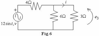
i. The
voltage across the 3![]() resistor e3 in Fig.6 is
:
resistor e3 in Fig.6 is
:
(A)
![]()
(B)
![]()
(C) ![]()
(D) ![]()
j. A stable system must have
(A) zero or negative real part for poles and zeros.
(B) atleast one pole or zero lying in the right-half s-plane.
(C) positive real part for any pole or zero.
(D) negative real part for all poles and zeros.
Answer any FIVE Questions out of EIGHT Questions.
Each question carries 16 marks.
Q.2 a. Find
the power dissipated in the ![]() resistor in the circuit shown in
Fig.7, using loop analysis. (8)
resistor in the circuit shown in
Fig.7, using loop analysis. (8)
 |
b. Find
![]() in the
network of Fig.8, if the current through
in the
network of Fig.8, if the current through![]() element is zero. (8)
element is zero. (8)
Q.3 a. Derive
the expression for transient current i(t) for a series R-L-C circuit with d-c
excitation of V, volts, assuming zero initial conditions. What will i(t) if ![]() , L=0.1H,
, L=0.1H, ![]() and
and ![]() ? (4+4)
? (4+4)
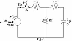
b. Find the transform current I(s) drawn
by the source shown in Fig.9 when switch K is closed at time t = 0. Assume
zero initial conditions. (8)
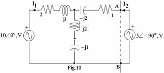
Q.4 a. State
Thevenin theorem. Obtain the Thevenin equivalent of the network across the
terminal AB as shown in Fig.10 (all element values are in ![]() ). (4+4)
). (4+4)
|
b. For the transform current function ![]() , draw its pole-zero
plot. Compute the inverse laplace transform. (8)
, draw its pole-zero
plot. Compute the inverse laplace transform. (8)
Q.5 a. Derive the
condition for maximum power transfer to the load ![]() from a voltage source
from a voltage source ![]() having source
impedance
having source
impedance ![]() .
Calculate this power if a
.
Calculate this power if a ![]() voltage source having source
impedance of
voltage source having source
impedance of
15+j20, ![]() drives the impedance-matched load. (5+3)
drives the impedance-matched load. (5+3)
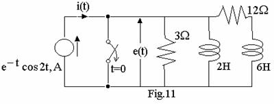
b. For the circuit of Fig.11, determine
e(t). Assume zero initial conditions. (8)
Q.6 a. Consider the transfer function of pure delay ![]() , where T = delay
w.r.t. the excitation. Sketch the amplitude and phase responses and the delay
characteristics. (8)
, where T = delay
w.r.t. the excitation. Sketch the amplitude and phase responses and the delay
characteristics. (8)
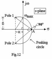
b. The peaking circle for
a single-tuned circuit is shown in Fig.12. State the conditions on ![]() and
and ![]() for
for ![]() to exist.
Determine
to exist.
Determine ![]() ,
circuit Q and half-power points for
,
circuit Q and half-power points for ![]() . What is the condition for a
high-Q circuit? (2+5+1=8)
. What is the condition for a
high-Q circuit? (2+5+1=8)
|
|||
|
|||
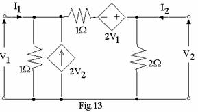
Q.7 a. Determine the y-parameters of the network of Fig.13. (8)
|
||||
|
||||
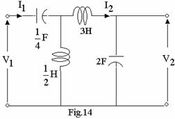
b. Find the voltage transfer function, current transfer function, input and transfer impedances for the network of Fig.14. (8)
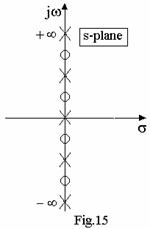
Q.8 a. From the given pole-zero configuration of Fig.15, determine the four possible L-C network configurations. (8)
b. Synthesise an L-C network
with 1-![]() termination given the transfer impedance function:
termination given the transfer impedance function: ![]() . (8)
. (8)
Q.9 a. Determine the range of constant ‘K’ for the polynomial to be Hurwitz.
![]() (8)
(8)
b. Define
Chebyshev cosine polynomial ![]() . Using recursive formula for
. Using recursive formula for ![]() , or otherwise,
obtain their values when n = 0 to 4. Plot
, or otherwise,
obtain their values when n = 0 to 4. Plot ![]() and
and ![]() for
for ![]() . (2+2+4
= 8)
. (2+2+4
= 8)