 Code: DE07 Subject:
NETWORK AND TRANSMISSION LINES
Code: DE07 Subject:
NETWORK AND TRANSMISSION LINES
Time: 3 Hours Max. Marks: 100
NOTE: There are 9 Questions in all.
· Question 1 is compulsory and carries 20 marks. Answer to Q. 1. must be written in the space provided for it in the answer book supplied and nowhere else.
· Out of the remaining EIGHT Questions answer any FIVE Questions. Each question carries 16 marks.
· Any required data not explicitly given, may be suitably assumed and stated.
Q.1 Choose the correct or best alternative in the following: (2x10)
a. If ![]() and
and ![]() are the Thevenin’s voltage
and resistance and
are the Thevenin’s voltage
and resistance and ![]() is the load resistance, then
Thevenin’s equivalent circuit consists of
is the load resistance, then
Thevenin’s equivalent circuit consists of
(A)
series combination of ![]() and
and ![]() .
.
(B) series combination of ![]() and
and ![]() .
.
(C)
parallel
combination of ![]() and
and
![]() .
.
(D)
parallel combination of ![]() and
and ![]() .
.
b. If ![]()
(A)
![]() (B)
(B)
![]()
(C) ![]() (D)
(D)
![]()
c. The integral of a step function is
(A) A ramp function. (B) An impulse function.
(C) Modified ramp function. (D) A sinusoid function.
d. For a prototype
low pass filter, the phase constant ![]() in the attenuation band is
in the attenuation band is
(A)
![]() (B)
0
(B)
0
(C) ![]() (D)
(D)
![]()
e. In the m-derived HPF, the resonant frequency is to be chosen so that it is
(A) above the cut-off frequency. (B) Below the cut-off frequency.
(C) equal to the cut-off frequency. (D) None of these.
f. In a symmetrical
![]() attenuator
with attenuation N and characteristic impedance
attenuator
with attenuation N and characteristic impedance ![]() , the resistance of each shunt arm is
equal to
, the resistance of each shunt arm is
equal to
(A) R O (B) (N–1)R O
(C) ![]() (D)
(D)
![]()
g. In terms of R,L,G and C the propagation constant of a transmission line is
(A)
![]() (B)
(B)
![]()
(C) ![]() (D)
(D)
![]()
h. A line has ![]() . If
. If ![]() , Voltage standing
wave ratio, S =
, Voltage standing
wave ratio, S =
(A) 1 (B) 0.5
(C) 2 (D)
![]()
i. In a series resonant circuit, the resonant frequency will be
(A) Geometric mean of half power frequencies.
(B) Arithmetic mean of half power frequencies.
(C) Difference of half power frequencies.
(D) Sum of half power frequencies.
j.
A function is given by ![]() . It would have a zero at
. It would have a zero at
(A) real axis of s-plane. (B) imaginary axis of s-plane.
(C) at infinity. (D) at the origin.
Answer any FIVE Questions out of EIGHT Questions.
Each question carries 16 marks.
Q.2 a. A
capacitance of ![]() is
charged to potential difference of 400 V and then connected in parallel with an
uncharged capacitor of
is
charged to potential difference of 400 V and then connected in parallel with an
uncharged capacitor of ![]() capacitance. Calculate the
potential difference across the parallel capacitors. (8)
capacitance. Calculate the
potential difference across the parallel capacitors. (8)
b. For
a given series RL circuit, determine
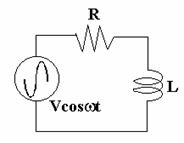
the
sinusoidal steady state solution ![]() . (8)
. (8)
Q.3 a. In
a series RLC circuit, ![]() and C=0.25F and the input driving
voltage is
and C=0.25F and the input driving
voltage is ![]() .
Assume that there is zero current through the inductor (L) and zero charge
across capacitor (C) before closing the switch. Find steady state current
flowing through circuit. (8)
.
Assume that there is zero current through the inductor (L) and zero charge
across capacitor (C) before closing the switch. Find steady state current
flowing through circuit. (8)
b. Find the Laplace transforms of
(i) ![]()
(ii) ![]() (shifted unit step function) (8)
(shifted unit step function) (8)
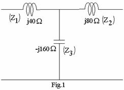
Q.4 a. Obtain the Y-parameters of the network shown in Fig.1. (6)
b. Write a short note on quarter wave transformer. (6)
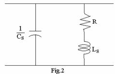
c. Find the input impedance for the circuit shown in Fig.2. (4)
|
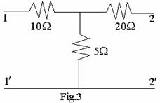
Q.5 a. Define h-parameters and transmission parameters of a two-port network. Determine the relation between them. (8)
b. Define image impedances and iterative impedances of an asymmetric two-port network. For the two port network, calculate the open circuit and short circuit impedances and hence the image impedances. (4+4)
|
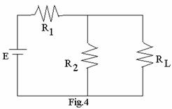
Q.6 a. For
the circuit in Fig.4 show the equivalency of Thevinin’s and Norton’s circuit. (8)
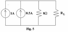
b. Calculate the value of
the load resistance ![]() for maximum power transfer in the
circuit shown in Fig.5. Calculate the value of maximum power. (8)
for maximum power transfer in the
circuit shown in Fig.5. Calculate the value of maximum power. (8)
Q.7 a. Define selectivity and Q of a series RLC circuit. Obtain the relation between the bandwidth, the quality factor and selectivity of a series RLC circuit. (8)
b. State and prove final value
theorem. Find the final value of the function where the Laplace transform is ![]() . (8)
. (8)
Q.8 a. Define the terms voltage standing wave ratio and reflection coefficient. Derive the relation between them. (8)
b. Describe various types of losses in a transmission line. How are these losses reduced. (8)
Q.9 a. Design
a symmetrical bridged T-attenuator to provide attenuation of 60dB and to work
into a line of characteristic impedance 600![]() . (8)
. (8)
b. Design
a Constant K Band Pass filter T-section having cut-off frequencies 2 kHz &
5kHz and a normal impedance of 600![]() . Draw the configuration of the
filter. (8)
. Draw the configuration of the
filter. (8)