 Code: AE08 Subject:
CIRCUIT THEORY & DESIGN
Code: AE08 Subject:
CIRCUIT THEORY & DESIGN
Time: 3 Hours Max. Marks: 100
NOTE: There are 9 Questions in all.
· Question 1 is compulsory and carries 20 marks. Answer to Q. 1. must be written in the space provided for it in the answer book supplied and nowhere else.
· Out of the remaining EIGHT Questions answer any FIVE Questions. Each question carries 16 marks.
· Any required data not explicitly given, may be suitably assumed and stated.
Q.1 Choose
the correct or best alternative in the following: (2x10)
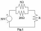
a. Power in ![]() resistor is 20W. The
resistance R is
resistor is 20W. The
resistance R is
(A)
![]() .
.
(B) ![]() .
.
(C)
![]() .
.
(D) ![]() .
.
b.
The Thevenin’s equivalent circuit to the left of AB in
Fig.2 has
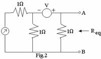
![]() given
by
given
by
(A)
![]() (B)
(B)
![]()
(C) 1![]() (D)
(D)
![]()
c. The energy stored in a capacitor is
(B)
![]() (B)
(B)
![]()
(C) ![]() (D)
(D)
![]()
|
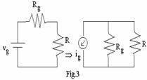
d. The Fig.3 shown are equivalent of each other then
(A)
 (B)
(B)

(C) ![]() (D)
(D)

|
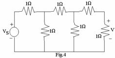
e. For the circuit shown in Fig.4, the voltage across
the last
resistor is V. All resistors are of ![]() .
.
The ![]() is given by
is given by
(A) 13V. (B) 8V.
(C) 4V. (D) 1V.
f. In the circuit shown in Fig.5, the
switch s
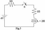
is closed at t = 0 then the steady state value
of the current is
(A) 1 Amp. (B) 2 Amp.
(C) 3 Amp. (D)
![]() Amp.
Amp.
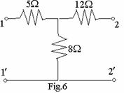
g. The z parameters of the network shown in Fig.6 is
(A)
![]() (B)
(B)
![]()
(C) ![]() (D)
(D)
![]()
h. For the pure reactive network the following condition to be satisfied
(A)
![]()
(B)
![]()
(C)
![]()
(D)
![]()
Where ![]() &
& ![]() even part of the
numerator and denominator and
even part of the
numerator and denominator and ![]()
![]() are odd parts of the numerator &
denominator of the network function.
are odd parts of the numerator &
denominator of the network function.
i. The network has
a network function ![]() . It is
. It is
(A) not a positive real function. (B) RL network.
(C) RC network. (D) LC network.
j. The Q factor for an inductor L in series with a resistance R is given by
(A)
![]() (B)
(B)
![]()
(C) ![]() (D)
(D)
![]()
Answer any FIVE Questions out of EIGHT Questions.
Each question carries 16 marks.
Q.2 a. For
the circuit shown in Fig.7. Determine the current ![]() and
and ![]() . (8)
. (8)
 |
b. In the network of the Fig.8, the switch K is open and network reaches a steady state. At t = 0, switch K is closed. Find the current in the inductor for t > 0. (8)
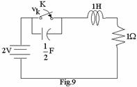
Q.3 a. The
network shown in the accompanying Fig.9 is in the steady state with the switch
K closed. At t = 0 the switch is opened. Determine the voltage across the
switch
![]() and
and
![]() at
at ![]() . (6)
. (6)
|
b. Define Thevenin’s theorem. (4)
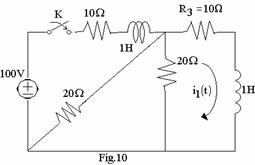
c. It is required to find the current ![]() in the resistor
in the resistor ![]() , by using
Thevenin's theorem: The network shown in Fig.10 is in zero state until t
= 0 when the switch is closed. (6)
, by using
Thevenin's theorem: The network shown in Fig.10 is in zero state until t
= 0 when the switch is closed. (6)
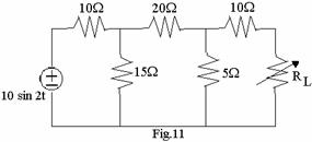
Q.4 a. For
the given network in Fig.11, determine the value of ![]() that will cause the power
in
that will cause the power
in ![]() to
have a maximum value. What will be the value of power under this condition. (8)
to
have a maximum value. What will be the value of power under this condition. (8)
|
||||
|
||||
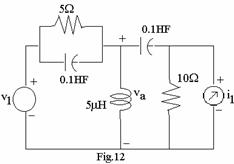
b. In the network shown in
Fig.12 ![]() and
and
![]() and the
and the
network is operating
in the steady state – For the element values as given, determine the node to
datum voltage ![]() .
(8)
.
(8)
Q.5 a. Determine the
amplitude and phase for F(J4) from the pole zero plot in s-plane for the
network function  . (8)
. (8)
b. A network function consists of two
poles at
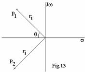
![]() as
given in the Fig.13. Show that the square of the amplitude response
as
given in the Fig.13. Show that the square of the amplitude response ![]() is maximum at
is maximum at ![]() . (8)
. (8)
Q.6 a. Following short circuit currents and voltages are obtained experimentally for a two port network
(i)
with
output short circuited ![]()
![]()
![]()
(ii)
with input
short circuited ![]()
![]()
![]()
Determine Y-parameters. (8)
b. The network of the Fig.14 contains a current controlled current source. For the network find the z-parameters. (8)
 |
Q.7 a. In the network of
Fig.15, K is changed from position a to b at t = 0. Solve for i, ![]() , and
, and ![]() at t = 0 + if R =
at t = 0 + if R =
![]() , L=1H,
C=0.1
, L=1H,
C=0.1 ![]() ,
and V = 100 V. (8)
,
and V = 100 V. (8)
b. Given ![]() what are the
restrictions on ‘X’. For z(s) to be a positive real function and find ‘X’ for
what are the
restrictions on ‘X’. For z(s) to be a positive real function and find ‘X’ for ![]() to have second
order zero at
to have second
order zero at ![]() .
(8)
.
(8)
Q.8 a. List
out the properties of LC immittance function and then realize the network
having the driving point impedance function ![]() by continued fraction method. (8)
by continued fraction method. (8)
b. For
the network function ![]() synthesize in one Foster and one
Cauer form. (8)
synthesize in one Foster and one
Cauer form. (8)
Q.9 a. The
voltage ratio transfer function of a constant-resistance bridged-T network is
given by  synthesize
the network that terminated in a
synthesize
the network that terminated in a ![]() resistor. (8)
resistor. (8)
b. Find the poles of system functions for low-pass filter with n =3 and n = 4 Butterworth characteristics. (Do not use the tables) (8)