DECEMBER 2006
 Code:
D-03 Subject:
ENGINEERING DRAWING
Code:
D-03 Subject:
ENGINEERING DRAWING
Time: 3 Hours Max. Marks: 100
NOTE:
1. (a) There are SEVEN questions in all and these are arranged in three Sections
A, B and C.
(b) Sections A and B are compulsory and carry 20 marks and 32 marks
respectively.
(c) Out of remaining 5 questions (of 16 marks each) in Section C students are
required to answer any 3 questions.
2. Detach this sheet from the question paper and write answers on this sheet
only on Pages 1 & 2. Attach it to the main drawing sheet. Remaining
questions are to be answered on the main drawing sheet.
3. All dimensions given are in mm. Use suitable values of any missing and
mismatching dimensions.
4. Use BIS Code: SP: 46-1988 for all drawings and do not rub off construction
lines.
|
SECTION A (Compulsory)
Note :1. Attach this sheet to the main drawing sheet.
2. Write Answers To Question No. 1 In This Sheet Only.
Q.1 Write
the correct or best alternative in the following : (10![]() 2=20)
2=20)
a. A leader line is shown as
(A) continuous thick line. (B) continuous thin line.
(C) thick chain line. (D) thin chain line.
b. Isometric drawing sizes are larger than isometric projection sizes by
|
(A) 18%. (B) 22.5%.
(C) 45%. (D) 82%.
|
c. When a regular hexagonal prism is cut by a plane parallel to the axis at some distance from it, the shape of the section is
(A)
regular hexagon
(B) irregular hexagonal prism
(C) octagon
(D) rectangle
d. Concentric circles when drawn in isometric projections appear as
(A)
concentric circles. (B) eccentric circles.
(C) concentric ellipses. (D) eccentric ellipses.
e. When will the front view of a straight line shows the true length of the line?
(A) when the line is placed parallel to V.P.
(B) when the line is placed perpendicular to V.P.
(C) when the line is inclined to H.P.
(D) when the line is inclined to both V.P. and H.P.
f. When the axis of a solid is parallel to both H.P. and V.P., which view reveals the true shape of the base?
(A)
side view (B)
top view
(C) front view (D) bottom view
g.
Which type of
thread is used for power transmission?
(A) Metric thread.
(B) BSW thread.
(C) BA thread.
(D) Acme thread.
h. In a cotter joint, clearances are provided for
(A) easy assembly of various parts.
(B) for proper tightening of parts.
(C) providing facility of wear adjustment.
(D) easy dis-assembly.
i. Which of the following is not a foundation bolt?
(A)
Lewis bolt
(B) Rag bolt
(C) Tap bolt (D) Hooke bolt
j. Larger taper in a key used to fix pulley to a shaft will
(A)
increase
tightening effect.
(B) decrease tightening effect.
(C) does not affect tightening.
(D) Easier to invert.
SECTION B (Compulsory)
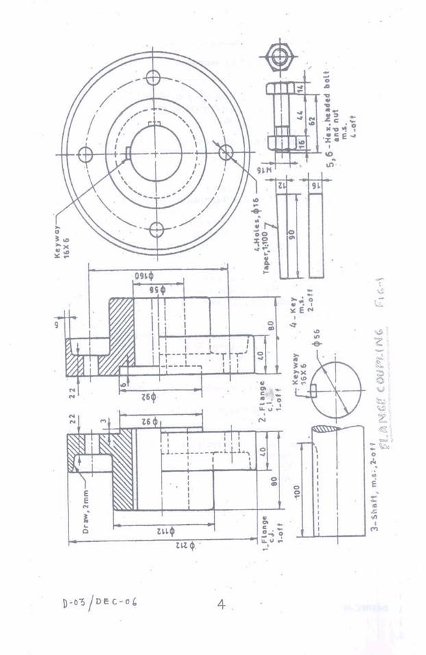
Q.2 Fig. 1 on page 4 shows the details of a protected rigid flange coupling. Draw the following views of the assembly to half the scale:
(i) Front view top half in section.
(ii) Left side view.
Show important dimensions. Print the title block and draw the projection symbol. (20+7+3+1+1)
SECTION C
Answer any THREE Questions. Each question carries 16 marks.
Q.3 Draw the locus of a point such that the difference between the distances of the point from two fixed points 35 mm apart is constant and is equal to 29 mm. Draw a tangent and normal to the curve at a point 14 mm from one focus. (16)
Q.4 A hexagonal prism of base side 30 mm and axis length 60 mm resting on H.P. on one of its base corners such that the solid diagonal through that corner is perpendicular to H.P. Draw its projections and also find the length of diagonal. (16)
Q.5 A cone of base diameter 50 mm and axis length 75 mm is resting on H.P. on its base. It is cut by a plane perpendicular to both H.P. and V.P. and is 10 mm to the left of axis. Draw its top view, front view and true shape of the section. (16)
Q.6 a. Draw a slotted nut and sawn nut in position for a bolt diameter of 24 mm. (8)
b. Draw two views of a feather key and woodruff key in position for shafts of 25 mm diameter. (8)
Q.7 Draw the thread profiles for an enlarged pitch of 40 mm for the following:
(i) Buttress thread
(ii) Knuckle thread
(iii) Square thread (16)