DECEMBER 2006
Code: A-08 Subject: CIRCUIT THEORY & DESIGN
Time: 3 Hours Max. Marks: 100
NOTE: There are 9 Questions in all.
· Question 1 is compulsory and carries 20 marks. Answer to Q. 1. must be written in the space provided for it in the answer book supplied and nowhere else.
· Out of the remaining EIGHT Questions answer any FIVE Questions. Each question carries 16 marks.
· Any required data not explicitly given, may be suitably assumed and stated.
Q.1 Choose the correct or best alternative in the following: (2x10)
a.
The Thevenin
equivalent resistance
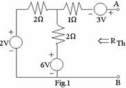
![]() for
for
the given network is equal to
(A)
![]() .
.
(B) ![]() .
.
(C)
![]() .
.
(D)
![]() .
.
b. The Laplace-transformed equivalent of a given network will have ![]() capacitor replaced
by
capacitor replaced
by
(A)
![]() . (B)
. (B)
![]() .
.
(C) ![]() . (D)
. (D)
![]() .
.
c. A network function contains only poles whose real-parts are zero or negative. The network is
(A) always stable.
(B)
stable,
if the j![]() -axis
poles are simple.
-axis
poles are simple.
(C)
stable,
if the j![]() -axis
poles are at most of multiplicity 2
-axis
poles are at most of multiplicity 2
(D) always unstable.
d. Maximum power is
delivered from a source of complex impedance ![]() to a connected load of complex
impedance
to a connected load of complex
impedance ![]() when
when
(A)
![]() (B)
(B)
![]()
(C) ![]() (D)
(D)
![]()
e. The admittance and impedance of the following kind of network have the same properties:
(A) LC (B) RL
(C) RC (D) RLC
f. The Q-factor (or figure of merit) for an inductor in parallel with a resistance R is given by
(A)
![]() . (B)
. (B)
![]() .
.
(C) ![]() LR (D)
LR (D)
![]() .
.
g. A 2-port network using z-parameter representation is said to be reciprocal if
(A)
![]() . (B)
. (B)
![]() .
.
(C) ![]() . (D)
. (D)
![]() .
.
h. Two inductors of values L1 and L2 are coupled by a mutual inductance M. By inter connection of the two elements, one can obtain a maximum inductance of
(A) L1+ L2 -M (B) L1+ L2
(C) L1+ L2+M (D) L1+ L2+2M
i. The expression![]() is
is
(A) a Butterworth polynomial.
(B) a Chebyshev polynomial.
(C) neither Butterworth nor Chebyshev polynomial.
(D) not a polynomial at all.
j. Both odd and even parts of a Hurwitz polynomial P(s) have roots
(A) in the right-half of s-plane. (B) in the left-half of s-plane.
(C) on the ![]() -axis only. (D)
on the
-axis only. (D)
on the![]() -axis
only.
-axis
only.
Answer any FIVE Questions out of EIGHT Questions.
Each question carries 16 marks.
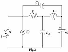
Q.2 a. Draw the dual of the network shown in Fig.2, listing the steps involved. (8)
|
|||
|
|||
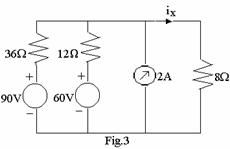
b. Using
superposition theorem for the network shown in Fig.3, find the value of ![]() . (8)
. (8)
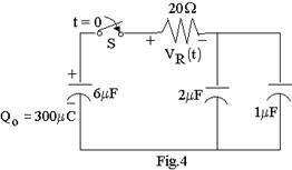
Q.3 a. Find
the transient voltage ![]() 40
40 ![]() after the switch S is closed at t = 0
in the network shown in Fig.4. (8)
after the switch S is closed at t = 0
in the network shown in Fig.4. (8)
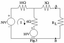
b. Obtain the Thevenin equivalent of the network shown in Fig.5. Then draw the Norton’s equivalent network by source transformation. (8)
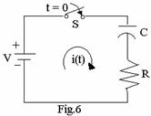
Q.4 a. Find
the initial conditions ![]() and
and ![]() for the circuit shown in Fig.6,
assuming that there is no initial charge on the capacitor. What will be the
corresponding initial conditions if an inductor with zero initial current were
connected in place of the capacitor? (8)
for the circuit shown in Fig.6,
assuming that there is no initial charge on the capacitor. What will be the
corresponding initial conditions if an inductor with zero initial current were
connected in place of the capacitor? (8)
|
|
||||
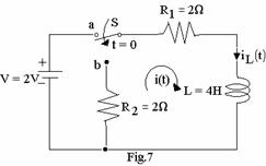
b. After steady-state
current is established in the R-L circuit shown in Fig.7 with switch S in
position ‘a’, the switch is moved to position ‘b’ at t = 0. Find ![]() and
and ![]() for t > 0.
What will be the value of i(t) when t = 4 seconds?
(8)
for t > 0.
What will be the value of i(t) when t = 4 seconds?
(8)
Q.5 a. Determine the
amplitude and phase for F(j2) from the pole-zero plot in s-plane for the
network function ![]() . (8)
. (8)
b. Determine,
by any method, the frequency of maximum response for the transfer function ![]() of a single-tuned
circuit. Find also the half power frequency. (8)
of a single-tuned
circuit. Find also the half power frequency. (8)
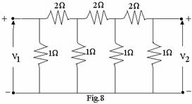
Q.6 a. For the resistive 2-port network shown in Fig.8, find v2/v1. (8)
|
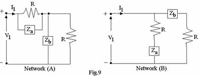
b. Show that ![]() holds good for
both the networks given in Fig.9 if V1/I1=R. (8)
holds good for
both the networks given in Fig.9 if V1/I1=R. (8)
|
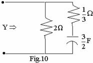
Q.7 a. Express
the driving-point admittance Y(s) in the form![]() , for the network shown in Fig.10.
Verify that Y(s) is p.r. and that
, for the network shown in Fig.10.
Verify that Y(s) is p.r. and that ![]() is Hurwitz. (8)
is Hurwitz. (8)
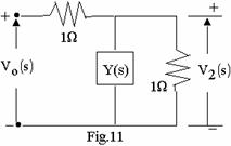
b. In Fig. 11, it is
required to find Y(s) to satisfy the transfer function ![]() Synthesise Y. (8)
Synthesise Y. (8)
|
||||
|
||||
Q.8 a. Synthesise
an LC network terminated in ![]() , given that
, given that ![]() . (8)
. (8)
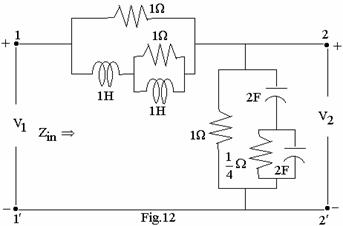
b. Find the z-parameters of the network shown in Fig.12. (8)
|
Q.9 a. Consider
the system function ![]() . Design:
. Design:
(i) an R-L network.
(ii) an R-C network. (12)
b. Sketch the response of
the magnitude function  where Cn
is the Chebhyshev polynomial, for n=1, 2 and 3. (4)